
Ducati Diavel Service Manual: Water radiators
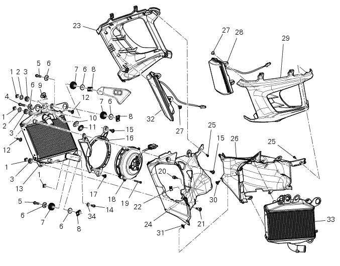
- Clip nut
- Spacer
- Vibration damper mount
- Screw
- Screw
- Spacer
- Vibration damper mount
- Clip nut
- Bush
- Spacer
- Rear sprocket
- Screw
- Water radiator (right)
- Screw
- Screw
- Air deflector (right)
- Special screw
- Electro-fan
- Screw
- Vibration damper mount
- Screw
- Plug
- Half-fairing (right)
- Internal air duct
- Screw
- Internal air duct
- Screw
- Front turn indicator
- Half-fairing (left)
- Special screw
- Clip nut
- Front turn indicator
- Water radiator (left)
- Washer
- Screw
Spare parts catalogue
Diavel abs radiator (right)
Diavel abs radiator (left)
Diavel abs half fairing
Diavel carbon abs radiator (right)
Diavel carbon abs radiator (left)
Diavel carbon abs half fairing
Important
Bold reference numbers in this section identify parts not shown in the figures alongside the text, but which can be found in the exploded view diagram.
The exploded view shows only the rh water radiator since the left one features the same components except the plug (22).
- Removing the water radiators
- Disassembling the water radiator unit
- Renewal of the cooling fan
- Reassembling the water radiator unit
- Refitting the radiator
 Refitting the cooling system hoses and unions
Position the pump/radiator sleeve (22) and the radiator/radiator sleeve (23).
Fit sleeve (23) and sleeve (22) to their corresponding fittings (n) and (o), and
bring them fully home on collars (p) ...
 Removing the water radiators
Loosen the screws (p) that retain the supports (s) of the front splashguard
to the air ducts (24) and (26).
Loosen the screws (30), to separate the two internal air ducts (24) and (26). ...
Other materials:
Lcd unit functions
Speedometer.
Gives road speed
Rev counter.
Indicates engine revs per minute.
Clock.
Water temperature indicator.
Indicates engine coolant temperature.
Important
Stop riding if the temperature reaches the maximum value, otherwise the
engine might be damaged.
...
On-board computers and the can line
The following on-board computers make up the electrical system of the diavel
and are connected with each other via the
can line (or network):
Master dashboard
Slave dashboard
Hands free (facilitated keyless start system)
Ecu (engine control unit)
Bbs (black box system or central elect ...
Flexible wiring/hoses positioning
The routing of the abs wiring has been optimised to ensure the minimum
obstruction.
Each section is designed to prevent interference with parts that might damage
wires or cause operating failures when
riding.
Table a
Table b
Table c
...