
Ducati Diavel Service Manual: Wiring diagram of the hands free system
The diagram illustrates the inputs, outputs and communication lines used by the hands free system.
1I - on/off button placed on the hands free system (located below the plastic cover)
2I - on/off button placed on the bike handlebar rh side
3I - steering position micro-switch
4I - steering position micro-switch
5I - active key (signals remote transmission)
6I - passive key (it transmits signals only if leant on the antenna)
1U - electric filler plug (optional)
2U - hands free relay (it replaces the ignition switch function)
3U - steering lock actuator
1C - can line
2C - communication line via antenna (radio-frequency)
The following is the overall layout of the motorcycle network:
The following is the general electrical system diagram and pinout of the hands free system. Note that the components relative to the electric steering lock are not included as they are not integrated into the hands free module.

- Direct supply from battery - red (r);
- Hands free system ground - black (bk);
- Hands free relay coil command - red/yellow (r/y);
- Can h line - grey/black (gr/bk);
- Can l line - grey/green (gr/g);
- Input for system on/off button on handlebar - light blue (lb);
1A, 2a antenna - key communication antenna connection - blue/black (b/bk) and red/yellow (r/y); fuel tank cap coil - fuel tank cap coil command
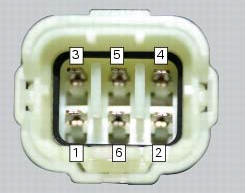
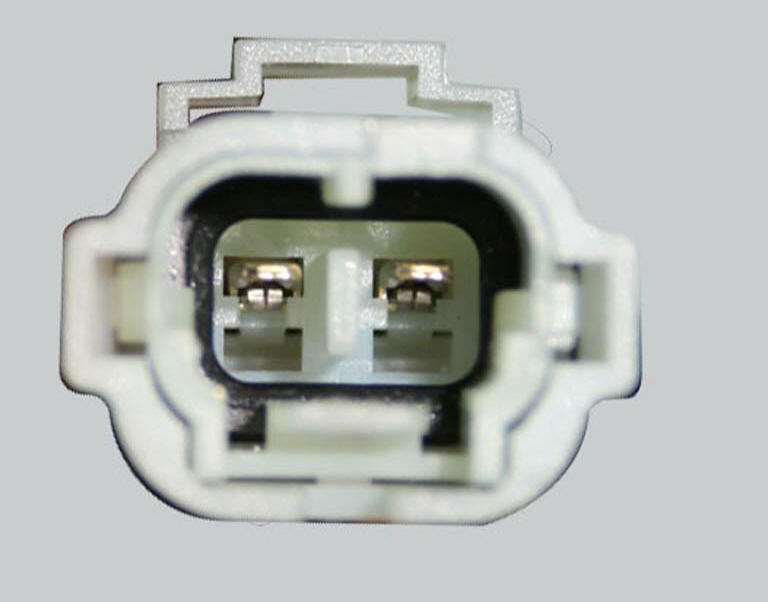
The photo shows the pinout for the hands free side connection
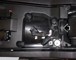
Location of hands free system connection
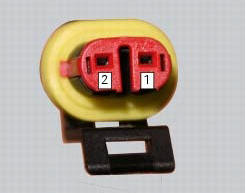
The photo shows the pinout for the hands free side antenna connection
The photo shows the pinout for the hands free side electric fuel tank cap connection
The hands free system is located in front of the fuel tank and is covered by a plastic shield. The on/off button built into the system is visible under the plastic shield. This button has the same functions as the button on the handlebar, but should only be used if the latter is not working or when starting the motorcycle without keys.
The plastic shield covering the hands free system is visible in the photo.
Note
In the usa version the door (1) is not present.

The hand free system on/off button is shown in the photo, with the plastic shield removed
The antenna used by the hands free system to communicate with the keys is placed in the document compartment under the seat.
This image shows the location of the hands free system antenna, behind the clear plexiglas windscreen
The hands free relay, which ideally replaces the function of the ignition switch of the traditional bikes, supplies +15 with key turned to on, and is positioned on its supporting bracket.

This image shows the location of the hands free relay (a). It is located on the relay supporting bracket.
Possible faults of the hands free system components
 How to reset the pin code
The pin code can be reset with the dds, i.E. It can be brought to the same
condition it was in when the bike came out
the factory. It is possible to complete the procedure with the relevant pin cod ...
 The hands free module
Introduction
The hands free module incorporates the control unit communicating with the
other nodes on the motorcycle, the on/off
button, the microswitches detecting full lock steering angle (for ...
Other materials:
Removing the front footrest brackets
Note
The assembly of the front footrests is described only for the right one
(2) but it is the same also for the left one.
Place the spring (4) bringing the end (a) onto the footrest (2).
Place the footrest (2) in the correct position, by inserting the end (c) of the
spring (4) in the hole ...
Overhauling the front brake components
Important
Critical safety components. The brake calliper manufacturer recommends
that you do not attempt to service the internal
components of the brake callipers. Incorrect overhaul of this component could
endanger rider safety.
Operations should be limited to renewal of the pads, fasteners ...
Adjusting the position of the gear change and rear brake pedals
The position of the gear change and rear brake pedals in relation to the
footrests can be adjusted to suit the preferred
riding position.
To modify the gear change pedal position act in the following mode:
hold the linkage (1) and slacken the counter nuts (2) and (3).
Note
Nut (2) has a lef ...