
Ducati Diavel Service Manual: Reassembling the electrical components support
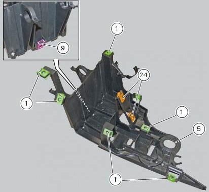
Check the presence of clips (1), (9) and (24) on the support (5).
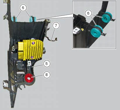
Check the presence of rubber pads (6) and (8) and of cable grommet (7).
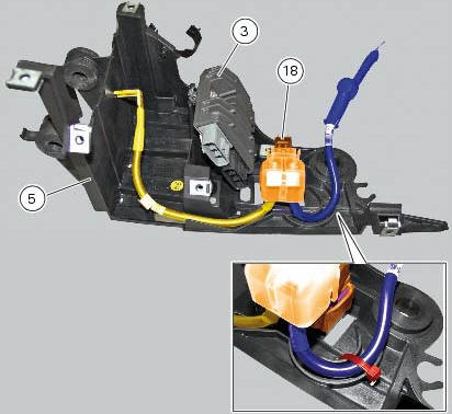
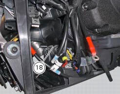
Check that the voltage regulator (3) and the solenoid starter (18) are in place on the support (5) with their wiring as shown.
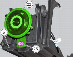
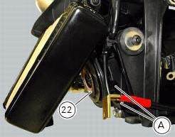
The horn (22) must be fixed to the support (5) tightening the screw (25) to 18 nm +/- 10% (sect. 3 - 3, Frame torque settings).
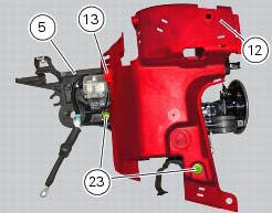
Check the presence of the grommet (13) on the cover (12).
Fit cover (12) on the support (5) by tightening the screw (23) to a torque of 4 nm +/- 10% (sect. 3 - 3, Frame torque settings).
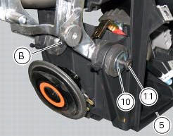
Fit the electrical components support (5) on the vehicle by engaging it in the retaining pin (b) on the cooler supporting bracket.
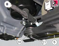
Apply the recommended threadlocker to the screw (21).
Start the screw (11) with washer (10) and the screw (21) with spacer (20).
Tighten the screw (11) to a torque of 10 nm +/-10% (sect. 3 - 3, Frame torque settings) and the screw (26) to a torque of 24 nm +/-10% (sect. 3 - 3, Frame torque settings).
Connect the connector (a) of horn (22) to the main wiring.
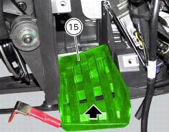
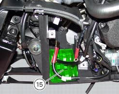
The mat (15) must be positioned as shown.
Reassemble the following elements located inside the electrical components support:
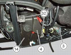
- The battery (14) as specified under section 6 - 2,battery;
- The voltage regulator (3) as specified under section 6 - 2,rectifier-regulator;
- The solenoid starter (18) as specified under section 6 - 3,solenoid starter;
After installing the battery, position the battery retaining bracket (4) by tightening the screws (32) to a torque of 5 nm +/- 10% (sect. 3 - 3, Frame torque settings).
Check wiring position as described in chapter: "routing of wiring on frame", sect. 6 -1.
 Removing the electrical components support
Remove the following elements located inside the electrical components
support:
The battery fixing bracket (4) and the battery (14) as specified under
section 6 - 2, battery;
The voltag ...

Other materials:
Reassembly of the connecting rods
Before starting, check that the crankshaft main bearing journals and big-end
journals are free of burrs or evident signs of
machining: if necessary, clean the surfaces with very fine emery cloth and oil.
Check that the grooves are in perfect condition with no signs of forcing.
Clean the cra ...
Total distance covered indicator: "odometer"
This function shows the total distance covered by the vehicle (in km or miles
depending on the specific application).
At key-on the system automatically enters this function.
The odometer reading is stored permanently and cannot be reset.
If the distance travelled exceeds 199999 km (or 19 ...
Lap registration function
This function describes the "lap" time registration.
If the function is activated (see "lap activation/deactivation description), the
lap time can be registered as follows:
pressing the flash headlight button (6) the first time starts the "lap timer"
for the first lap, and the dashboard show ...