
Ducati Diavel Service Manual: Refitting the rear footrests
Note
The refitting of the rear footrests is described for the right side but it is the same for both.
If previously removed, refit the rubber footrest (11) on the rear rh footrest (6), by pushing it until pad (b) engages in the other side.
Note
The rubber footrest (11) side featuring the least width must be faced to the outer side of the footrest (12).
Apply recommended grease to the seats (g) of the o-rings and in area (h) on the rear rh footrest (12).
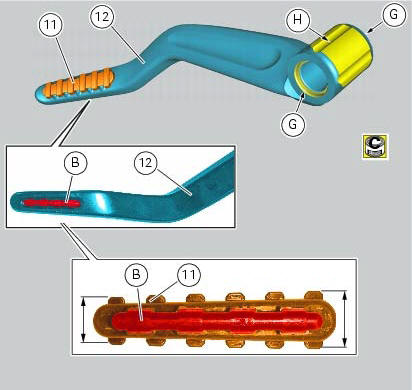
Place o-rings (9) in the relevant seats of the footrest (12).
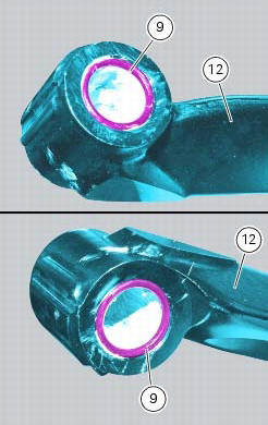
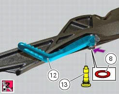
Position footrest (12) as shown, on the rear subframe rh bracket; make sure that the previously fitted o-rings do not come out of the relevant seats on the footrest (12).
Fit washer (8) between footrest (12) and the rear subframe rh bracket.
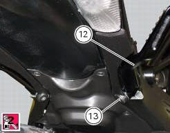
Fix the footrest (12) by starting the pin (13) smeared with specified threadlocker.
Tighten the pin (13) to a torque of 30 nm +/- 10% (sect. 3 - 3, Frame torque settings).
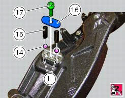
If previously removed, apply recommended grease into the holes (l) and insert balls (14) and springs (15) into the relevant holes of the rear subframe rh bracket.
Apply prescribed threadlocker on the screw thread (17).
Fit the cap (16) and tighten the screw (17) to a torque of 10 nm +/- 10% (sect. 3 - 3, Frame torque settings)
 Removing of the rear footrests
The removal of the rear footrests is described for the right side but it is
the same for both.
Undo the pin (13) and remove the rh rear footrest (12) from the frame.
Recover washer (8) and the ...
 Stands
Side stand
Side stand switch
Screw
Plate
Screw
Inner spring
Outer spring
Nut
Rotation pivot
Screw
Screw
Screw
Nut
Clearance adjuster
Spare parts catalogue
Diavel a ...
Other materials:
Appropriate diagnosis tools
97900.0211 Dds (ducati diagnosis system) without cables
97900.0227 Power cable and diagnosis
97900.0222 Power cable and diagnosis 1060838 (measurement module)
97900.0218 Vacuum sensor
552.1.039.1A Pressure sensor
97900.0220 Pressure/vacuum tube
97900.0221 Union
...
Removal of the clutch master cylinder assembly
Warning
The clutch master cylinder manufacturer advises against servicing of
the clutch master cylinder (1) due to the safetycritical
nature of this component. Incorrect overhaul of this component could endanger
rider safety.
Maintenance operations of the master cylinder are limited to replac ...
Refitting the clutch transmission unit
Position pipe (4) on the clutch slave cylinder (r).
Position the two seals (19) and tighten the screw (18) to a torque of 23 nm +/-
10% (sect. 3 - 3, Frame torque settings).
Refit the bleed valve (17) and the dust gaiter (16).
To position the pipe retaining clamps (4) refer to the table on ...