
Ducati Diavel Service Manual: Active key
Introduction
The active key (1) communicates with the hands free system by radio. In order to function, the key must be within a 1.5 Metre radius from the antenna (located in the document compartment under the seat).
In the event of a flat key battery or of an internal transmitter circuit fault, the active key may be used in transponder mode (exactly like the passive key). In this mode, the key must be physically placed on the antenna in order to work correctly.
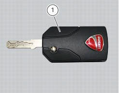
By pressing button (a) of the active key (1) the metallic part (2) opens completely - position (b).
Hold depressed button (a) to move the metal part (2) and set it to the middle position (c); once in place, release button to lock. This function facilitates the opening of the tank plug.
The metal part returns inside the grip by pushing it in.
Wiring diagram
No wiring diagram is available for the component
Error codes
"Key diagnosis" error: "wrong key". The key has been detected but is not associated with the hands free system. The fault can only be viewed from the dds after switching the dashboard on with the pin code.
- Check that the key is correct.
- Reprogramme the key
- If none of the tests described above identifies the problem, replace the hands free system.
"Key diagnosis" error: "encryption error". The encrypted code stored in the key is not recognised by the hands free system. The fault can only be viewed from the dds after switching the dashboard on with the pin code.
- Check that the key is correct.
- Check that the key is not damaged.
- Check that the battery key is charged.
- Check that the antenna is working correctly.
- Try to use the active key as a transponder with the antenna. To reach the antenna remove the seat (sect. 5 - 3, "Removal of the seat").
- Reprogramme the key.
- If none of the tests described above identify the problem, contact ducati.
Electrical characteristics and checking component
The active key is fitted with a cr 2032 type 3 volt lithium ion battery. Use only batteries with the same code and the same electrical characteristics.
In the event of fault
A specific message is displayed on the dashboard if the key battery is flat. Replace the battery.
If the active key does not work or is not detected, it may still be used in transponder mode, placing the key itself against the lower part of the clear plexiglas windscreen.
Replacing the battery in the active key
Only use 3 volt cr 2032 lithium ion batteries.
Note
The keys do not need to be reprogrammed after replacing the battery.
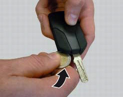
Unfold the mechanical part of the active key.
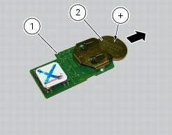
Use a large sized coin to open the plastic shells of the grip (2 d coin) as shown in the figure.
Important
Insert the coil only in the indicated point. Do not other use other objects inserted in points that are different than what is shown, as it could damage the integrated circuit and/or the protective gasket.
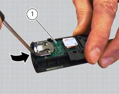
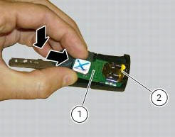
Once the plastic shells have been separated, remove the printed circuit board (1) prying it up gently with a small flat screwdriver, as shown in the figure.
Important
Insert the point of the flat screwdriver just under the printed circuit board, being very careful not to damage it. Do not apply force on the battery or battery holder.
Remove the battery (2) from the printed circuit board (1) and replace it with a new one.
Pay attention to polarity: the positive pole (+) must face upward.
Important
Use only batteries of the recommended type (cr 2032).
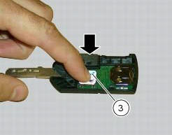
Reinsert the printed circuit board (1) from the side with the battery (2) into the plastic shell.
Apply slight pressure on the antenna (3) of the printed circuit board until you hear a click.
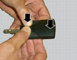
Align the two shells of the grip and press on the area indicated by the arrows to close them.
Make sure that you hear a "click" upon closing and that the key is well closed.
 The hands free relay
Introduction
This relay provides key on +15 power to all the devices on the motorcycle.
Functionally, it replaces the conventional
ignition switch.
Wiring diagram
The hands free relay receiv ...
 Passive key
Introduction
The passive key (1) is used when the active key is not working correctly or
is not available.
The passive key works as a transponder, and must therefore be placed physically
onto ...
Other materials:
Checking the engine timing
Set the engine to the configuration described for the "checking and adjusting
the valve clearances", previously indicated.
Install tool 88765.1188 (G) in the spark plug bore to determine the piston tdc,
the gauges (h) on the tool 88765.1518
And the timing check tool (degree wheel (l) 887 ...
Low battery level
The activation of this (amber yellow) "warning" indicates that the status of
the battery vehicle is low.
It is activated when the battery voltage is ¼ 11.0 Volt.
Note
In this case, ducati recommends charging the battery as soon as possible
with the specific device, as it is possible th ...
Refitting the rear wheel
Lubricate the wheel shaft threaded end with prescribed grease.
Insert the wheel shaft by matching (a) with pins (b).
Install spacer (3) with the conical surface faced to the wheel conical
surface, washer (2), apply prescribed grease to nut
(1) and insert it by hand (1).
Tighten the ...