
Ducati Diavel Service Manual: Adjusting the chain tension
Make the rear wheel turn until you find the position where chain is tightest. Set the vehicle on the side stand. Push down the chain at the point of measurement and release. Measure the distance between the "aperture" upper profile and pin centre.
The read distance must be: 9 to 11 mm.
Important
If the drive chain is too tight or too slack, adjust it so that tension reading will fall within specified range.
To adjust the tension remove the rear splash guard (sect. 7 - 13, Removal of the swingarm).
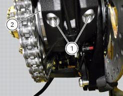
Slacken off the two clamp screws (1) that secure the rear wheel hub to the swingarm.
Fit the hook spanner code 88713.1038 Inserting its tooth in the eccentric hub (2).
Rotate the eccentric hub (2) to obtain the correct chain tension.
Turn counter clockwise to tighten the chain; clockwise to loosen (from chain side).
Important
An incorrectly tensioned chain will lead to accelerated wear of the transmission components.
If the screws (1) are removed, lubricate with specified grease underhead and thread, then tighten the screws (1) to the torque of 35 nm +/- 5% (sect. 3 - 3, Frame torque settings) proceeding with sequence 1-2-1.
Warning
The correct tightening of the fixing screws of the eccentric hub is essential for the safety of the rider and the passenger (sect. 3 - 3, Frame torque settings).
Refit the rear splash guard (sect. 7 - 13, Refitting the swingarm).
 Adjusting the steering head bearings
Excessive handlebar play or shaking forks in the steering head indicate that
the play in the steering head bearings
requires adjustment. Proceed as follows:
loosen the clamp screw (1) that holds t ...
 Checking brake pad wear and changing brake pads
Warning
Brake fluid is corrosive and will damage paintwork. Avoid contact
with eyes and skin. In the case of accidental contact,
wash the affected area thoroughly with plenty of running water.
Im ...
Other materials:
Disassembly of the generator cover
Undo the three stator retaining screws (25) and the two retaining screws (9)
of the two cable grommet bracket (10) from
inside the generator cover.
Remove the stator (2) and the cable grommet bracket (10).
The generator-side crankcase cover is fitted with a bearing (27), held in
pla ...
Reassembly of the crankcase halves
If removed, apply threadlocker on the screw (36), insert it with the washer
(37) on the crankcase half and tighten it to The torque of 8 nm
(min. 7 Nm - max. 9 Nm) (sect. 3 - 3, Engine torque settings).
If removed, apply threadlocker on the dowel thread (35), tighten it to a
torque of 20 ...
Limited liability
The liability of ducati under this emission control systems
warranty is limited solely to the remedying of defects in
material or workmanship by an authorized ducati motorcycle
dealer at its place of business during customary business
hours. This warranty does not cover inconvenience or l ...