
Ducati Diavel Service Manual: Adjusting the rear shock absorber
The adjuster (1) located on the lower connection holding the shock absorber to the swingarm adjusts the damping during the rebound phase (return).
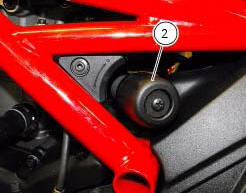
The knob (2), located on the left side of the motorcycle, adjusts the preload of the shock absorber external spring.
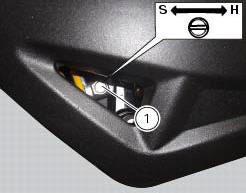
Turn the adjuster (1) clockwise to increase damping h; or counter clockwise to reduce damping s.
Standard setting from the fully closed position (clockwise): -unscrew adjuster (1) by 8 clicks.
Spring preload: 15 mm.
The two nuts (2) on the upper part of the shock absorber serve to adjust the preload on the external spring. To change spring preload, slacken the upper locking ring nut. Then tighten or slacken the lower ring nut to increase or decrease spring preload.
Important
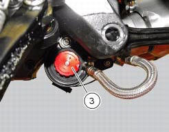
The knob (3) located on the expansion reservoir of the shock absorber adjusts the damping during the compression phase.
Turning the adjusters (1) or the knobs (2) and (3) clockwise to increase preload damping; they decrease turning them in the opposite direction.
Standard setting: from fully closed (clockwise) loosen: register (1) of 12 clicks; knob (2) fully open (counter clockwise); register (3) of 25 clicks.
Spring preload: 18 mm (max.18 Mm - min.25 Mm
Warning
The shock absorber is filled with high-pressure gas and can cause injuries if inexpertly dismantled.
Important
If the motorcycle is to be ridden with a pillion rider and luggage, we
recommend setting the rear shock absorber spring
preload to the maximum to ensure the best handling and proper ground clearance
at all times. It may also be necessary
to adjust the rebound damping accordingly.
 Adjusting the front fork
The front fork used on this motorcycle has rebound, compression and spring
preload adjustment.
This adjustment is done using the outer adjusters:
Rebound damping;
Inner spring preload;
Co ...
 Fairings
...
Other materials:
Headlight control
This function allows you to reduce current consumption from
the battery, by automatically managing headlight switchingoff.
At key-on, the high beam and low beam lights are off.
When the engine is started, the low beam lights turn on
automatically; from this moment, "normal" operati ...
Guided diagnosis
Note
The on-screen icons used during this procedure are explained in a table at
the end of this section.
The dds diagnosis instrument guides the operator step-by-step through the
various diagnostic procedures,
providing descriptions and documentation for motorcycle components, wiring
diagra ...
Explanation of the function of the ride-by-wire system
Mechanism
Via metal cables, the throttle grip operates a roller mounted on one end of a
spindle located near the horizontal cylinder
throttle valve spindle.
The aps sensor, which measures the position of the throttle grip itself, is
mounted on the opposite end of this spindle.
A mechanic ...