
Ducati Diavel Service Manual: Backlighting setting function for the dashboard on handlebar - dashboard 2
This function allows backlighting setting of the dashboard on handlebar.
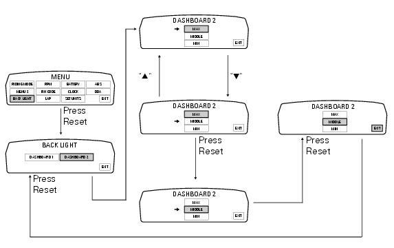
To access the function it is necessary to view the ""setting" menu", using buttons (1) "s" or (2) "t" select the "back light" function and press the reset button (3) to enter the following page.
Use button (1) "s" or (2) "t" to select the "dashboard 2" function and confirm by pressing the reset button (3).
Once you enter the "dashboard 2" function, setting is highlighted on the display (max, middle or min in green); use button (1) "s" or (2) "t" to shift the arrow to the left onto the new setting and confirm by pressing the reset button (3).
To exit the setting function, press the reset button (3) when "exit" is highlighted.
Select "max" setting and the background of the dashboard on handlebar permanently sets backlighting to maximum power to improve readout view - recommended with bright exterior lighting.
Select "middle" setting and the background of the dashboard on handlebar permanently sets reduced backlighting to 30% of its maximum power for dimmed visibility - recommended with poor exterior lighting.
Select "min" setting and the background of the dashboard on handlebar permanently sets reduced backlighting to 50% of its maximum power for dimmed visibility - recommended with very poor exterior lighting and/or dark.
 Background setting function for the dashboard on tank - dashboard 1
This function allows setting the "background" of the dashboard on tank.
To access the function it is necessary to view the ""setting" menu", using
buttons (1) "s" or (2) "t" select the "back
lig ...
 Digital rpm indication function
This function displays the number of rpms for improved accuracy when setting
idle rpm.
To access the function it is necessary to view the ""setting" menu", using
buttons (1) "s" or (2) "t" select ...
Other materials:
Adjusting the position of the gearchange and rear brake
pedals
The position of the gearchange and rear brake pedals in
relation to the footrests can be adjusted to suit the
requirements of the rider.
Adjust the pedals as follows:
Gear change pedal (fig. 97)
Hold the linkage (1) and slacken the lock nuts (2) and (3).
Note
Nut (2) has a left-hand thr ...
Reporting of safety defects
If you believe that your vehicle has a defect which could
cause a crash or could cause injury or death, you should
immediately inform the national highway traffic safety
administration (nhtsa) in addition to notifying ducati north
america. If nhtsa receives similar complaints, it may open
an in ...
Moving off
Disengage the clutch by squeezing the clutch lever.
Push down the gear change lever firmly with the tip of
your foot to engage first gear.
Raise the engine revs by turning the throttle twistgrip
while gradually releasing the clutch lever. The motorcycle
will start moving.
Release the ...