
Ducati Diavel Service Manual: Communication antenna
Introduction
The communication antenna enables the hands free system to detect and communicate with the active or passive key.
The active key is detectable within a range of 1.5 Metres, whereas the passive key (or active key with flat battery) can only be detected if placed in contact with the lower part of the clear plexiglas windscreen covering the antenna.
An antenna fault will compromise correct key detection.
Wiring diagram
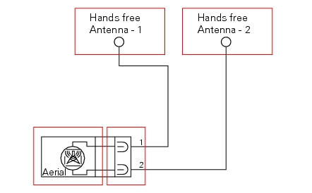
The communication antenna is connected to the hands free system by two cables and a dedicated connection.
- Blue/black (b/bk)
- Red/yellow (r/y)
Error codes
"Hands free diagnosis" error: "antenna": antenna not detected (open circuit)
or antenna short circuited. The following icon
appears on the tank dashboard:
- Check that the antenna is in working condition by measuring its electrical resistance.
- Check the integrity of the electrical circuit and the relative connections.
Note
Checking the integrity of the electrical circuit entails the following actions:
- Check the wires for continuity and check the state and integrity of the connections.
- Check that the wires are not short circuited to one another, to vdc or to ground.
Short circuit to vdc: with the dashboard on, use a voltmeter to measure the voltage between the wire being tested and ground.
Short circuit to ground: with the battery cables disconnected, use an ohmmeter to check for continuity between the wire being tested and ground.
Open circuit: with the battery cables disconnected, use an ohmmeter to check that there is no continuity between the two ends of the wire being tested.
- If none of the tests described above identifies the problem, replace the hands free system.
Electrical characteristics and checking component
The resistance between the two terminals of the component side connection must be approximately 2 ohm.
In the event of fault
In the event of a component fault, the hands free system can no longer detect and recognise the keys. The pin code procedure must be used to start the motorcycle.
Installation location
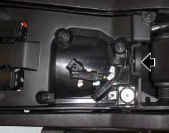
The image shows the location of the hands free system antenna.
Location of hands free system antenna on antenna side.
Component replacement methods
No special measures are necessary in order to replace the hands free system communication antenna.
 The hands free module
Introduction
The hands free module incorporates the control unit communicating with the
other nodes on the motorcycle, the on/off
button, the microswitches detecting full lock steering angle (for ...
 On/off switch on handlebar
Introduction
The on/off switch on the handlebar is used to switch the dashboard on and
off, if a key has been detected, and start the
engine.
With the switch turned to "run off" (centre positio ...
Other materials:
Coverage
Warranty defects shall be remedied during customary
business hours at any authorized ducati motorcycle dealer
located within the united states of america in compliance
with the clean air act and applicable regulations of the
united states environmental protection agency and the
california air r ...
Key-on/key-off using the red key on the handlebar with the passive key
A key-on can be performed by pressing the red button (6) on
the handlebar in the hands free on/off position and in
the presence of the passive key (4, fig. 77).
Note
The passive key (4, fig. 77) Has a range of a few cm,
therefore the key (4, fig. 77) Must be positioned near the
antenna (2). R ...
Refitting the brake disks
Before refitting the brake disc to the wheel, clean all contact surfaces
thoroughly and smear a medium strength
threadlocker on the threads of retaining screws (5).
Operating on the left side, fit the phonic wheel (6).
Tighten the fixing screws (5) of the brake disk (7) to the wheel followi ...