
Ducati Diavel Service Manual: Disassembly of the generator cover
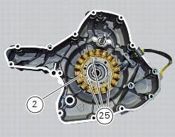
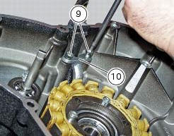
Undo the three stator retaining screws (25) and the two retaining screws (9) of the two cable grommet bracket (10) from inside the generator cover.
Remove the stator (2) and the cable grommet bracket (10).
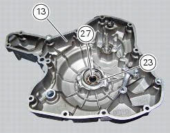
The generator-side crankcase cover is fitted with a bearing (27), held in place by circlip (23), which is located on the end of the crankshaft.
Remove the circlip (23) with circlip pliers.
Remove the bearing (27) using a universal puller.
Be careful when fitting the new bearing (27) to ensure it is positioned with the shielded side facing away from the cover.
Secure the bearing with the circlip (23), ensuring that it is correctly fitted in its seat in the generator cover (13).
Remove the water pump components as described in sect. 9 - 3.3, Removal of the water pump.
 Removal of the generator cover
Note
This operation is described for an engine removed from the frame since all
reassembly procedures are easier with the
engine on the bench.
Disconnect the connector (a) from the generator ...
 Removing the flywheel - generator assembly
Use the tool 88713.3367 Fixed to the m10 side stand fixing holes (d).
Secure the tool to the flywheel with the screws (e).
Unscrew the alternator-flywheel retaining nut (15).
Warning
While uns ...
Other materials:
Refitting the expansion tank
If the support (15) has been removed, place the hose clamps (14) on the
bracket (15) orienting them as indicated.
Fully press the pins (a) to block the clamps (14) until pins surfaces (b) are at
the same level of the clamps (14) surfaces.
Apply recommended threadlocker to the thread of the ...
Removal of the rear wheel eccentric hub and rear wheel shaft
Before removing the eccentric hub, you must first remove the parts listed
below.
Slacken off the screws (34).
Remove the spacer (20) and the inner ring (21) on the chain side and remove the
wheel shaft (31) with the brake disc
(30) from the opposite side.
Remove the circlip (19 ...
Indicating devices
Checking the indicating devices
In the event of a fault, the internal connections of the device must be
checked in all operating conditions. To do this, it is
necessary to disconnect the switch connector from the main wiring harness (sect.
6 - 1, Routing of wiring on frame).
Then analyse th ...