
Ducati Diavel Service Manual: Dashes shown instead of speed indication or indicated speed is incorrect
Fault codes
Dds: speed sensor diagnosis -> max. Speed (max. Speed error - signal not correct) - minimum speed (min speed error - signal not correct) - congruence (correlation speed error - signal not correct).
Dashboard: the error "speed sensor" is shown on the service display. The eobd warning light activates.
Fault indication
If the dashboard does not receive "vehicle speed" information via the can line:
- The error is not indicated on the service display.
- The speed indicator on the dashboard displays fixed dashes.
If:
- Dtc is enabled and the abs detects an error on at least one wheel speed sensor (abs fault indicator light lit and abs disabled).
Or
- An error occurs on at least one wheel speed sensor with no abs.
The error "speed sensor" is shown on the dashboard service display.
Warning
The dashboard speed indicator also displays fixed dashes if vehicle speed exceeds 299 km/h.
Warning
Dtc is disabled in the event of a wheel speed sensor erro
r.
Wiring diagram
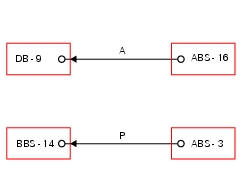
Bbs bbs unit connection, db dashboard connection, abs abs connection. Bbs 14 green/purple - g/v, db 9 blue - b.

Pin numbering for wiring harness side dashboard connector.
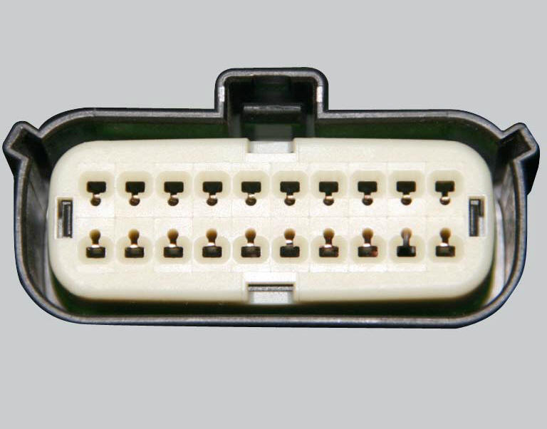
Pin numbering of wiring harness side bbs unit connection.
Checks
For diagnosing wheel speed sensors, consult the section relative to diagnosing the abs unit.
Check the integrity of the electrical circuit and connections (short-circuits to ground, short-circuits to vdc, open circuits).
If the above test did not identify the problem, contact ducati.
Note
Check integrity of electric circuit - short-circuit to vdc = with dashboard on, using a voltmeter, a voltage is measured between the wire tested and ground.
Check integrity of electric circuit - short-circuit to ground = with the battery cables disconnected, using an ohmmeter, continuity is detected between the wire tested and ground.
Check integrity of electric circuit - open circuit = with the battery cables disconnected, using an ohmmeter, no continuity is detected between the two ends of the wire tested.
Propagation of wheel speed signals and generation of vehicle speed signal
The diagram illustrates how the vehicle speed information is generated and how it is transmitted to the dashboard.
Using the replicated rear wheel speed signal and the circumference of the wheel itself, the bbs unit calculates the vehicle speed (2 in diagram). This parameter is used by the ducati traction control (dtc) function together with the front wheel speed and the circumference of the front wheel itself, in order to implement engine torque limiting strategies when required.
The vehicle speed calculated by the bbs is transmitted over the can line (3 in diagram) and acquired by the dashboard, which displays the speed information accordingly.
 Gear indicator display on dashboard shows dashes, engaged gear not displayed
correctly, idle speed irregular
with gearbox in neutral
Gear indicator display on dashboard shows dashes, engaged gear not displayed
correctly, idle speed irregular
with gearbox in neutral
Fault codes
Dds: gear sensor diagnosis -> short circuit to ground or open circuit (s.C.
Gnd or c.O.) - Short circuit to vdc (s.C. Vdc)
- congruence (generic error - signal not correct).
Dash ...
 Abs fault indicator not working
Fault codes
Dds: displays a fault code described in the description of the abs system.
Dashboard: no fault code displayed.
Wiring diagram
Checks
The abs fault indicator indicates the occurr ...
Other materials:
Front brake control
Front brake master cylinder
Brake lever
Special screw
Sealing washer
Screw
Phonic wheel
Brake disc
Pin
Left brake calliper
Boot
Bleed valve
Spare stand
Control unit - front callipers pipe
Microswitch
Oil duct union
Screw
Hose clip
Right brake calliper
Speci ...
Injectors
Introduction
The injectors used on the diavel are top feed units, meaning that fuel is fed
into the top of the injector itself. The
injectors contain a winding which raises a needle when electrically energised.
This opens the atomiser nozzle, through
which pressurised fuel is dispensed, gener ...
Refitting the clutch transmission unit
Position pipe (4) on the clutch slave cylinder (r).
Position the two seals (19) and tighten the screw (18) to a torque of 23 nm +/-
10% (sect. 3 - 3, Frame torque settings).
Refit the bleed valve (17) and the dust gaiter (16).
To position the pipe retaining clamps (4) refer to the table on ...