
Ducati Diavel Service Manual: Removing of the abs control unit
Drain the hydraulic fluid that is inside the front and rear braking system tubes by disconnecting them from the master cylinder and the calliper (sect. 4 -3, Changing the brake fluid).
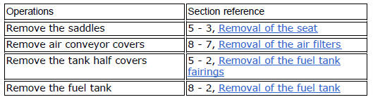
Disconnect the connector (a) of the abs control unit (6).
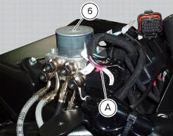
Loosen the screws (16) that retain the abs control unit support (12) and remove it from the vehicle.
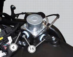
Undo the four special screw (17) fixing the pipes (10), (9), (8) and (7), on the abs control unit (6), removing the gaskets (11).
Warning
Every time that gaskets (11) are removed, they must be replaced with new gaskets (11).
Important
Do not open the abs control unit: if it is faulty, replace it.
Note
If it is necessary to replace one or more pipes, follow the instructions indicated in paragraph "flexible wiring/hoses positioning" of this section.
 Replacing the rear phonic wheel sensor
Disconnect the rear abs sensor (5) connector (c) from the main electric
wiring.
Open all the retainer clamps of the rear abs sensor cable (5): refer to table of
sect. 7 - 6, Flexible wiring ...
 Refitting the abs control unit
If the brake hoses (7), (8), (9) and (10) on the abs control unit are changed
or removed, ensure that the fittings on the
control unit are positioned correctly.
Warning
If incorrectly positioned, ...
Other materials:
Running lights not working
Fault codes
Dds: no fault code displayed.
Dashboard: no fault code displayed.
Location of connections and components
(A) low / high beam and parking light connections
rear running light and stop light connection.
Pin numbering of wiring harness side bbs unit connection.
Checks
The ...
Identification data
All ducati motorcycles have two identification numbers, for
frame (fig. 1) And engine (fig. 2).
Note
These numbers indicate the motorcycle model and
should be quoted when ordering spare parts.
...
Adjusting the position of the gearchange and rear brake
pedals
The position of the gearchange and rear brake pedals in
relation to the footrests can be adjusted to suit the
requirements of the rider.
Adjust the pedals as follows:
Gear change pedal (fig. 97)
Hold the linkage (1) and slacken the lock nuts (2) and (3).
Note
Nut (2) has a left-hand thr ...