
Ducati Diavel Service Manual: Disassembly of structural components and the frame
Before carrying out dimensional checks on the frame, you must remove all the superstructures fitted, referring to the removal procedures outlined in the sections of this manual.
The rear subframes (2) and (3) are structural components of the frame (1).
Both serve to support motorcycle superstructures and must therefore be in perfect condition.
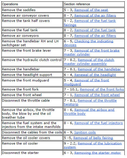
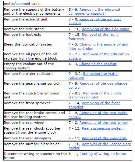
The following flow chart illustrates the logical sequence in which the parts are to be removed from the motorcycle and a reference to the section where the removal procedure is described.
Refitting is the reverse of removal.
 Frame inspection
Frame
Rh subframe
Lh subframe
Grub screw
Nut
Special screw
Rubber pad
Nut
Special screw
Screw
Left-hand bracket
Hose clip
Hose clip
Right-hand bracket
Special screw
...
 Removal of the tool tray
To remove the tool tray unit from the lateral footrests, loosen the screws
(40) and remove the splashguard (20).
Undo the screws (15) and remove the cover (16).
Move the wiring branch ...
Other materials:
Rear wheel
Right-hand wheel nut
Washer
Spacer
Valve
Wheel
Circlip
Spare parts catalogue
Diavel abs front and rear wheels
Diavel carbon
abs
front and rear wheels
Important
Bold reference numbers in this section identify parts not shown in the
figures alongside the text, but which can ...
Tank filler plug
Note
To open or close the tank filler plug using the active
key, set the metal part in the middle position, as shown on
page 86.
Opening
Lift the cover (1, fig. 100) And insert the active or passive key
into the lock. Give the key a 1/4 turn clockwise to unlock.
Lift the plug (2, fig. 101) ...
Injection and ignition
Introduction
Ignition is via a single stick coil per cylinder installed in the spark plug
well. Each thermal unit is supplied by a single
injector, placed under the throttle valve. The amount of fuel injected and the
ignition advances are determined by the
control unit specifically for each c ...