
Ducati Diavel Service Manual: Removal of the tool tray
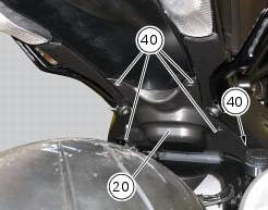
To remove the tool tray unit from the lateral footrests, loosen the screws (40) and remove the splashguard (20).
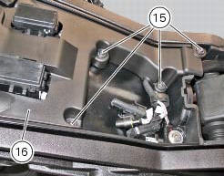
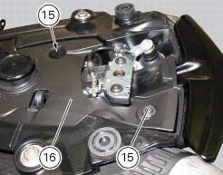
Undo the screws (15) and remove the cover (16).
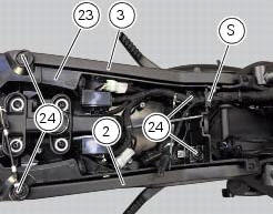
Move the wiring branch from the seat (s) on the tool tray.
Loosen the screws (24) to remove the tool tray unit (23) from the lateral brackets (2) and (3).
 Disassembly of structural components and the frame
Before carrying out dimensional checks on the frame, you must remove all the
superstructures fitted, referring to the
removal procedures outlined in the sections of this manual.
The rear subfram ...
 Removing the frame and the lateral footrests
Loosen the two special screws (6) to separate the frame (1) from the lateral
brackets (2) and (3).
On the left side of the vehicle block retaining pins (9) and loosen the nuts (8)
on the right ...
Other materials:
Changing bulbs
Changing the headlight bulbs
Before replacing a burnt out light bulb, ensure that the replacement bulb has
the same voltage and power rating as
specified for the lighting device in question (sect. 3 - 1.1, Lights/instrument
panel).
Warning
The halogen light bulbs in the headlight become hot ...
Recovery procedure in the event of electric steering lock fault
If any fault occurs during activation of the electric steering lock: for
example, if the pin jams, if the handlebar is moved
while the pin is deployed or if there is excessive strain on the electric pin
actuator motor, the electric steering lock is
automatically disengaged and the hands free s ...
Overhaul of cylinder head components
Cylinder heads
Remove any carbon deposits from the combustion chamber and its ducts.
Remove any scale from the coolant ducts.
Check for cracking and inspect the sealing surfaces for scoring, ridges or other
damage.
Check that the cylinder barrel mating surfaces of the cylinder head are ...