
Ducati Diavel Owners Manual: Engine setting function (engine power control)
This function customises engine power and output.
To access the function it is necessary to view the "setting" menu page 48, using
button (1, fig. 14) ?"
"or (2, fig. 14) ?" "select the "riding mode"function
and press the
reset button (12, fig. 12) To go to next page.
Use button (1, fig. 14) ?" "or (2,
fig. 14) ?" "to select the riding
mode to be changed and press the reset button (12, fig. 12) To access the next
page. Now use button (1, fig. 14) ?"
"and (2, fig. 14) ?"
"to select the "engine" indication
and press the reset button again (12, fig. 12) To confirm
selection.
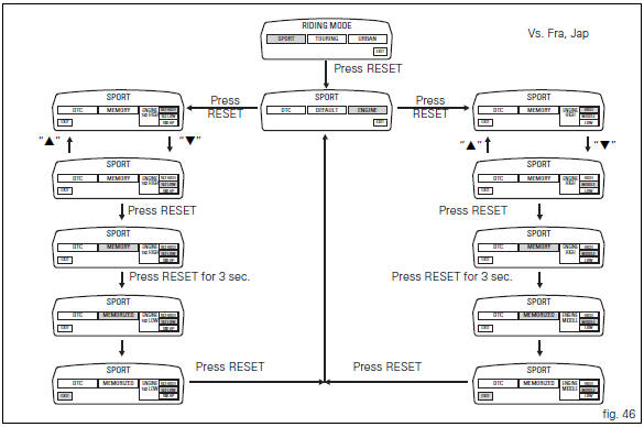
When accessing the function, the engine setting (engine 162 high, 162 low o 100 hp) appears at the right-hand side of the display, inside a rectangle.
 Note
Note
In japan and france versions, the display displays the settings (engine high, middle or low).
Using button (1, fig. 14) ?"" or
(2, fig. 14) ?" " select one of
the three available engine settings; after selecting the new
setting, press the reset button (12, fig. 12) To highlight
"memory" indication.
At this point, store the new setting by pressing and holding the reset button (12, fig. 12) For 3 seconds with "memory" displayed. If the setting has been stored successfully, the display will show "memorized" in green for 2 seconds and the exit option will be highlighted automatically.
To exit the setting function, press the reset button (12, fig.
12) Where "exit" is highlighted.
 Tips for use on the road
Activate the dtc, select level 8 and ride the motorcycle in
your usual style; if the level of dtc intervention seems
excessive, try reducing the setting to levels 7, 6, etc., Until
you find the lev ...
 Default function (resetting ducati default parameters)
This function resets the parameters set by ducati for each
riding style.
To access the function it is necessary to view the "setting" menu page 48, using
button (1, fig. 14) ?"
...
Other materials:
Belly fairing
Rh belly fairing
Lh belly fairing
Special screw
Nylon washer
Screw
Central belly fairing
Oil cooler shield
Special screw
Clip
Washer
Clip
Screw
Bracket
Screw
Spare parts catalogue
Diavel abs belly fairing
Diavel carbon
abs
belly fairing
Important
Bold refere ...
Hydraulic clutch control
Special screw
Sealing washer
Clutch master cylinder
Clutch hydraulic pipe (metal braid)
Screw
Spare stand
Washer
Microswitch
Pin
Bleed valve
Screw
Roller
O-ring
Clutch control rod
Clutch lever
Dust cap
Bleed valve
Special screw
Sealing washer
Boot
Plug
...
Checking protection and safety device components
Checking the side stand switch
Remove the switch (1) from the side stand undoing screw (2) and disconnect
the main wiring connector from the switch
(see paragraph "routing of wiring on frame", sect. 6 - 1).
Use an analogue or digital multimeter (sect. 6 - 11, Using a multimeter to check
the ...