
Ducati Diavel Service Manual: Overhauling the front wheel
Wheel bearings
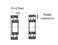
Before checking the dimensions, check the wear on wheel bearings. Check for wear by hand after cleaning and degreasing the bearings in their seats.
Turn the inner race.
Check the amount of radial and axial play. Excessive play will cause vibration and make the bike unstable.
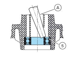
To remove the bearings (5) and the sealing rings (4) from the wheel hub follow the instructions below.
Position a drift (a) against the inner race of the bearing (5).
Tap with a hammer until knocking out the bearing (5).
Apply the drift at different points to keep the bearing square during removal.
Important
Once removed, the used bearings and sealing rings must not be refitted.
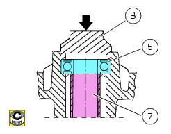
Before fitting new bearings, check that the housing is clean and free from scoring and damage.
Grease the bearing seat and then push the new bearing into its seat.
Using a tubular drift (b) that only bears on the outer race of the bearing, drive the bearing (5) fully into its seat.
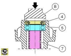
Use the same method to install the sealing rings (4).
Ensure that spacer (7) is fitted between the two wheel bearings.
Note
Wheels must be rebalanced after repair, maintenance and overhaul operations.
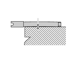
Inspecting the wheel axle
Check the wheel shaft for straightness.
Turn the pin on a reference surface and measure maximum distortion using a feeler gauge (see sect. 3 - 1.1, Front wheel).
Overhauling the wheel
After you have checked the bearings, check the rim as follows.
Visually inspect the wheel for cracks, scoring and deformation; change the wheel if damaged.
Insert the shaft in the wheel and mount it on two fixed reference blocks.
Using a dial gauge, measure rim run-out and out-of-round relative to the pin axle (see sect. 3 - 1.1, Front wheel).
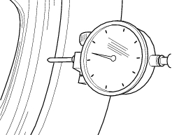
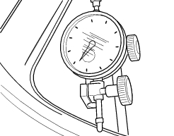
If the values measured are not within the tolerance limits, renew the wheel.
 Removal of the front wheel
Support the bike so that the front wheel is raised from the ground.
Remove the front brake calliper (b) by unscrewing the two screws (a) securing
the calliper to the fork leg; do not
disconnect ...
 Refitting the front wheel
When all the necessary inspections have been completed, refit the wheel as
follows.
Fit the spacers (3) and (9) to the seal rings on the sides of the wheel hub.
Install the complete whee ...
Other materials:
Key-on/key-off using the key on the hands free lock with the active key
Key-on can be performed by pressing the button (7) on the
hands free lock (1, fig. 77) And with the presence of the
active key (3, fig. 77).
Note
The active key (3, fig. 77) Has a range of approx. 1.5 M,
therefore it must be located within this range.
Key-off can be performed by pressing the ...
Indicator cons. - Instantaneous fuel consumption
This function indicates the "instantaneous" fuel consumption.
The calculation is made considering the quantity of fuel used
and the distance travelled during the last second. The datum is
expressed in "l/100" (litres / 100 km); it is possible to change
the units of measurem ...
Overall dimensions (mm)
Weights
Weight in running order without fluids and battery: 210 kg.
Carrying full load: 400 kg.
Warning
failure to observe weight limits could result in poor
handling and impair the performance of your motorcycle, and
you may lose control of the vehicle.
Important
Do not use addi ...