
Ducati Diavel Service Manual: Refitting the front brake master cylinder
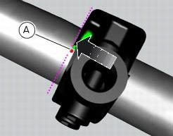
Insert the front brake master cylinder unit (1) on the right side of the handlebar to bring the terminal internal edge in correspondence to the bolted joints (a).
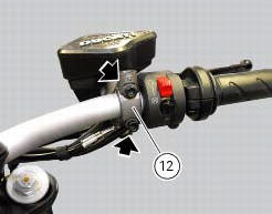
Fit the terminal (12) on the handlebar inserting the screws (15).
Tighten the terminal (12) retaining screws to a torque of 10 nm +/- 10% (sect. 3 - 3, Frame torque settings) following the sequence 1-2-1 starting from the upper screw.
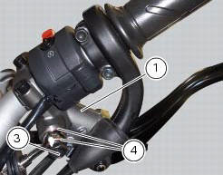
Locate the pipe with sealing washers (4) on the master cylinder assembly (1) and secure it with the special screw (3), without tightening it.
Warning
An incorrectly positioned hose can cause clutch faults and interfere with moving parts.
Orientate the pipe (24) as illustrated in the figure and then tighten the special screw (3) to a torque of 23 nm +/- 10% (sect. 3 - 3, Frame torque settings).
In order to fit the pipe (24) and the retaining clips, follow instructions in sect. 7 - 6, Flexible wiring/hoses positioning.

 Removal of the front brake master cylinder
Warning
The brake master cylinder manufacturer advises against servicing the
brake master cylinder due to the safety critical
nature of this component. Incorrect overhaul of these critical safety ...
 Maintenance operations
Warning
Brake fluid is corrosive and will damage paintwork. Avoid contact
with eyes and skin. In case of accidental contact, wash
the affected area with abundant running water and consult a doctor ...
Other materials:
Cleaning and replacing the spark plugs
Spark plugs are essential to smooth engine running and
should be checked at regular intervals.
The condition of the spark plugs provides a good indication of
how well the engine is running.
Have the spark plugs inspected or replaced at a ducati dealer
or authorised service centre; they will ...
Indicator cons. - Instantaneous fuel consumption
This function indicates the "instantaneous" fuel consumption.
The calculation is made considering the quantity of fuel used and the distance
travelled during the last second. The datum
is expressed in "l / 100" (litres / 100 km); it is possible to change the units
of measurement for "consump ...
Tool kit and accessories
The tool kit (2) is located under the seat (1) while the owner’s
manual is housed in the compartment under the seat.
The tool kit includes:
Fuse pliers;
Two helmet anti-theft cables;
Screwdriver;
Screwdriver handle;
14/16 Mm box wrench;
6 Mm rod;
3 Mm allen wrench;
4 Mm allen ...