
Ducati Diavel Service Manual: Refitting the front sprocket
Grease the o-ring (16) and install it on the front sprocket spacer (15).
Fit the spacer, from the o-ring side, on the secondary shaft and drive it fully home against the inner ring of the bearing.
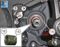
Check that the splines of the gearbox secondary shaft and the sprocket are in perfect condition.
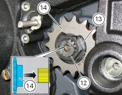
Fit the engine pinion (14) on the gearbox secondary shaft by orienting it as indicated. Install the safety washer (13).
Tighten the nut (12) to the torque of 186 nm +/- 5% (sect. 3 - 3, Frame torque settings).
Bend the washer (13).
Fit the chain and close it using the tool with code 88713.1344 That was used to open the chain.
The tool is composed of a holder (a), punch (b), body (c) and two wrenches (d) and (e) and link plate holder (f).
Connect the two halves of the chain with the external link and manually fit the plate onto the pins.
Warning
Lubricate the pins abundantly; try to avoid touching them with your hands.
Fit the holder (a) onto the external link.
Fit the punch (b) into the body (c) and the plate holder (f).
Fit the body (c) onto the holder (a) which holds the chain in position.
Manually turn the bolt (g) until the plate holder (f) is seated against the plate itself.
Use wrenches (d) and (e) to turn the bolt (g) clockwise until the chain pin is in contact with the holder (f).
Remove the holder (a) from the tool.
Manually turn the bolt (g) until the punch (b) locates against the pin, taking care that they are aligned with each other.
Use wrenches (d) and (e) to turn the bolt clockwise until the punch (b) is seated against the chain plate.
To complete reassembly, repeat the entire procedure with the second pin.
Warning
Carefully check the two pins: the figure shows the correct result of the procedure.
Adjust the chain tension (sect. 4 - 3, Adjusting the chain tension).
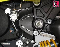
Apply the recommended threadlocker to the screws (11).
Fit the sprocket cover (10) tightening the screws (11) to the torque of 6 nm+/- 10% (sect. 3 - 3, Frame torque settings).
 Removing of the front sprocket
Undo the screws (11) and remove the chain cover (10).
Loosen the chain (sect. 4 - 3, Adjusting the chain tension).
Remove the chain with the tool code 88713.1344.
The tool is composed of a ...
 Replacing of the rear sprocket
Lock the wheel axle rotation.
Remove the clip (1).
Loosen the locking nut (2) with a socket wrench.
Fully unscrew the nut (2) and remove the washer (3) and the flange (5) with the
sproc ...
Other materials:
Indicating devices
Checking the indicating devices
In the event of a fault, the internal connections of the device must be
checked in all operating conditions. To do this, it is
necessary to disconnect the switch connector from the main wiring harness (sect.
6 - 1, Routing of wiring on frame).
Then analyse th ...
Reassembly of the cylinder head
The exhaust side can be identified by the three threaded holes on the flange.
The intake side can be identified by the presence of four threaded holes on
the flange.
All the photos in this chapter refer to a vertical cylinder head.
Valve guide sealing rings
Position the cylinder head o ...
Clutch lever button
Introduction
The clutch button is located on the clutch lever. Together with the signal
from the side stand button and the neutral signal
generated by the gear sensor (transmitted to the engine control unit over the
can line), the clutch lever position signal is
used to enable or disable engi ...