
Ducati Diavel Service Manual: Refitting the side stand
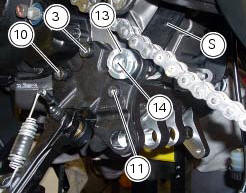
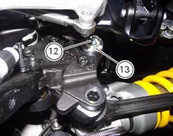
Place the stand plate on the rear shock absorber support; bring adjuster (14) in line with bracket (s) and start the screw (12) in the nut behind the bracket (s).
Insert the screws (11), (3) and (10) fully home in this order, but do not tighten.
Loosen the screw (12) with the relative nut, tighten the adjuster (14) to a torque of 0.6 Nm +/- 10% (sect. 3 - 3, Frame torque settings) and tighten the screw (12) to a torque of 2 nm +/- 10% (sect. 3 - 3, Frame torque settings) while holding the nut.
Locate service tool no. 88713.3166 On the ring nut (13) and fit the torque wrench to the tool. While holding the adjuster (14), tighten the ring nut (13) to a torque of 100 nm +/- 5% (sect. 3 - 3, Frame torque settings).
Tighten screws (11), (3) and (10) in this order to a torque of 44 nm +/- 10% (sect. 3 - 3, Frame torque settings).
Finally, tighten the screw (12) to a torque of 45 nm +/- 10% (sect. 3 - 3, Frame torque settings) while holding the nut.
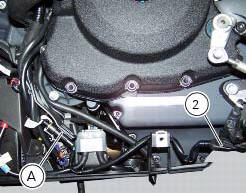
Connect connector (a) of the side stand switch to the main wiring harness.
To place the stand switch wiring refer to the table (sect. 6 - 1, Routing of wiring on frame).
 Removing of the side stand
Disconnect connector (a) of the stand switch (2) from the main wiring.
Loosen the screws (3), (10), (11) and (12) securing the stand bracket (4) to
the engine and remove the complete side
...
 Frame inspection
Frame
Rh subframe
Lh subframe
Grub screw
Nut
Special screw
Rubber pad
Nut
Special screw
Screw
Left-hand bracket
Hose clip
Hose clip
Right-hand bracket
Special screw
...
Other materials:
Reassembling the front footrest brackets
To reassemble the brackets (6) and (21) carry out the removal procedure in
the reverse order; tighten the screws (7) to a
torque of 25 nm +/- 10% (sect. 3 - 3, Frame torque settings).
...
Fairings
Rh front half-fairing
Clip
Screw
Right-hand support
Screw
Screw
Rh air inlet
Lh air inlet
Screw
Clip
Left-hand support
Lh front half-fairing
Lh tank fairing
Screw
Nylon washer
Special screw
Washer
Spacer
Spring
Rubber pad
Rh tank fairing
Tank fairing
...
Headlight aim
The motorcycle must be perfectly upright with the tires inflated to the
correct pressure and with a rider seated, perfectly
perpendicular to the longitudinal axis.
Position the motorcycle 10 metres from a wall or a screen.
On the wall or surface, draw a horizontal line at the same height fr ...