
Ducati Diavel Service Manual: Alternator
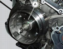
It is equipped with a 12 v, 430 w generator, consisting of a fixed element (stator, a) located on the generator cover and of a movable element (rotor, b) fixed to the crankshaft.
Note
To check the battery charging system for faults, use the dds diagnosis instrument and follow the instructions given in the paragraph, "testing the battery charging system" (sect. 6 - 11).
The absolute value of voltage measured across the terminals of two of the three yellow cables (the measured value will be the same whichever combination of cable is used) must be within the range indicated in the table below.
(Ambient temperature: 35 C - 70 C)
Important
Before testing, disconnect the alternator wiring from the electrical system when the ignition key is set to off.

Values significantly lower than those indicated above can be due to:
- Partially demagnetised rotor;
- Short-circuited windings.
In the above cases the whole alternator assembly (rotor and stator) should be renewed.
If checks have a favourable outcome, reconnect the alternator to the regulator with ignition key on off. Make sure that no cables are damaged or disconnected.
Removal of the alternator
Disconnect the cables of the alternator-side electric system (sect. 6 -1, Routing of wiring on frame).
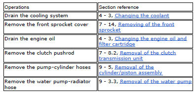
Remove the generator cover, the stator (a) and the rotor (b) (sect. 9 - 8, Removal of the generator cover).
Refitting the


Refitting the generator
Fit the rotor (b), the stator (a) and the alternator-side crankcase cover.
Connect the cables of the generator side electric system (refer to the table in chapter "routing of wiring on frame", sect. 6 - 1).
 Battery
Battery safety rules
Warning
Before carrying out any operations on the battery, keep in mind the
safety standards (sect. 1 - 3, General safety rules).
When under charge, batteries produce explo ...
 Rectifier-regulator
The rectifier (1) is placed in the electrical components compartment.
The rectifier/regulator consists of an aluminium casing containing the diodes
that rectify the current produced by the
alter ...
Other materials:
Removal of the timing gears
Slide out driving gear (a) of timing gear pair (13) and remove the woodruff
key (14).
Relieve the staking on the lock washer (12) of the nut (11).
Restrain the driven timing gear by inserting a pin in one of the holes, and
unscrew the nut (11).
Remove the nut (11), washer (12) ...
Refitting the clutch master cylinder assembly
Insert the clutch master cylinder assembly (3) and the clamp (6) on the left
handlebar, so that the top mating faces
match the mark (z) on the handlebar as shown.
Couple terminal (6) to the clutch master cylinder control and fix them with
the screws (v).
Tighten the retaining screws ...
Refitting the gearchange mechanism
Make sure that the gearchange linkage assembly (6) is installed with the ball
joint with a left-hand thread (a) facing the
lever (8).
Apply the recommended grease to the non-threaded surface of the pin (4).
Fit the first o-ring (5) in the pin (4).
Start the pin (4) in the gearchange leve ...