
Ducati Diavel Service Manual: Turn indicators not working
Fault codes
Dds: no fault code displayed.
Dashboard: no fault code displayed.
Wiring diagram
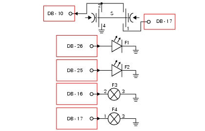
Db dashboard connection, bbs bbs unit connection, s turn indicator button, f1 front left turn indicator, f2 front right turn indicator, f3 rear left turn indicator, f4 rear right turn indicator. 2 On grey button - gr, 1 on red/blue button - r/b, 4 on black button - bk, db 26 white/black w/bk, db 25 green/black - g/bk, bbs 16 white/green - w/g, bbs 17 White/black w/bk.
Location of connections and components
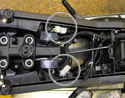
Location of rear turn indicator and number plate light connection.
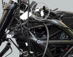
Location of left hand handlebar switchgear set connection.
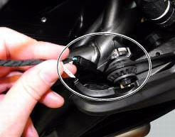
Location of front right turn indicator connection.
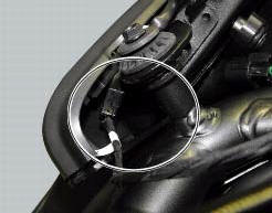
Location of front left turn indicator connection.
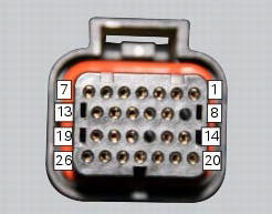
Pin numbering for wiring harness side dashboard connector.
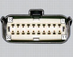
Pin numbering of wiring harness side bbs unit connection.
 Horn not working
Fault codes
Dds: horn diagnosis -> short circuit to ground (s.C. Gnd).
Dashboard: the error "claxon" (horn) is shown on the service display. The eobd
warning light activates.
Wiring diagram
...
 High beam flash not working - start/stop lap function not working
Fault codes
Dds: no fault code displayed.
Dashboard: no fault code displayed.
Wiring diagram
Db dashboard connection, s high beam flash button. 7 Orange - o, 1
red/blue - r/b.
Location of ...
Other materials:
Vehicle pre-delivery
Transport packaging integrity check (if required);
Removal from the transport packaging (if required);
Motorcycle integrity check;
Check of the supplied kit completeness (refer to the parts list supplied
together with the bike packaging);
Only if the bike is supplied in a crate: handle ...
Immobilizer override procedure
This procedure makes it possible to "temporarily" turn on the motorcycle if
the hf (hands free) system is not working.
Note
The pin code function must be activated by entering your 4 digit pin in
the dashboard, otherwise the vehicle cannot be
turned on temporarily in the case of a malfunction ...
Suspensions
Front
Hydraulic upside-down fork provided with external adjusters
for rebound and compression damping and preload (for inner
springs of fork legs).
Stanchion diameter:
50 mm, coated.
Rear wheel travel:
120 mm
Rear
The shock absorber is adjustable for rebound and
compression, with remot ...