
Ducati Diavel Service Manual: Horn not working
Fault codes
Dds: horn diagnosis -> short circuit to ground (s.C. Gnd).
Dashboard: the error "claxon" (horn) is shown on the service display. The eobd warning light activates.
Wiring diagram
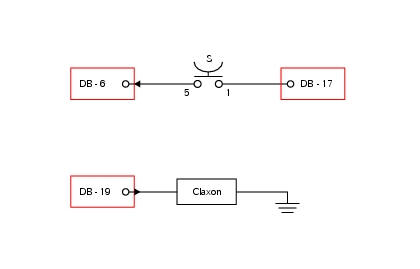
Db dashboard connection, s horn button. 5 Blue/white - b/w, 1 red/blue - r/b, db 19 purple/black - v/bk.
Location of connections and components
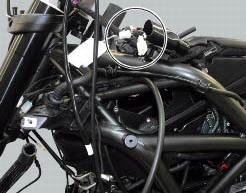
Location of left hand handlebar switchgear set connection.
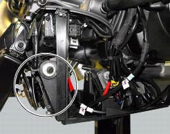
Location of horn with relative connection.
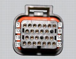
Pin numbering for wiring harness side dashboard connector.
Note
Check integrity of electric circuit - short-circuit to vdc = with dashboard on, using a voltmeter, a voltage is measured between the wire tested and ground.
Check integrity of electric circuit - short-circuit to ground = with the battery cables disconnected, using an ohmmeter, continuity is detected between the wire tested and ground.
Check integrity of electric circuit - open circuit = with the battery cables disconnected, using an ohmmeter, no continuity is detected between the two ends of the wire tested.
 Low beam lights not working
Location of connections and components
(A) injection relay; (b) etv relay (throttle valve operating engine); (c)
radiator fan relay; (d) hands free relay.
Fuses located at the rear left of ...
 Turn indicators not working
Fault codes
Dds: no fault code displayed.
Dashboard: no fault code displayed.
Wiring diagram
Db dashboard connection, bbs bbs unit connection, s turn indicator button, f1
front left turn i ...
Other materials:
Cylinder/piston assemblies
Piston
Gudgeon pin circlip
Gudgeon pin
Set of piston rings
Cylinder-crankcase gasket
Water pump outlet union
Hose clip
Horizontal cylinder coolant inlet hose
Vertical cylinder coolant inlet hose
Cylinder barrel
Cylinder head gasket
Bush
Spare parts catalogue
Diavel a ...
Refitting the fuel tank fairings
Make sure that the following components are fitted on the tank fairing (22):
Spacers (18);
Seals (20).
Fit the clips (19) to the central cover (22) at the positions shown,
inserting the tabs (h) into the slots (l).
Apply threadlocker to the screws (14).
Place the tank fairing (22) ...
Dashboard diagnosis
This function identifies any abnormal vehicle behaviours.
The dashboard activates any abnormal vehicle behaviours in real time (errors).
At key-on (at the end of the check) one or more "errors" are displayed in red
(only if they are active).
When an "error" is triggered, the indication (r ...