
Ducati Diavel Service Manual: Guided diagnosis
Note
The on-screen icons used during this procedure are explained in a table at the end of this section.
The dds diagnosis instrument guides the operator step-by-step through the various diagnostic procedures, providing descriptions and documentation for motorcycle components, wiring diagrams for the electronic systems and information on the locations of specific components.
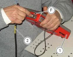
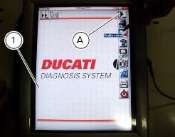
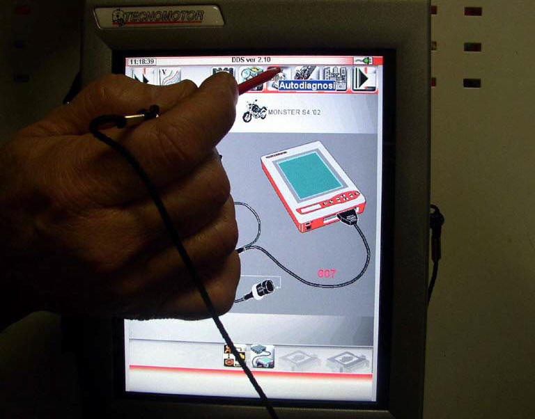
Turn on the dds diagnosis instrument (1) referring to the paragraph "tester power supply".
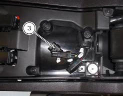
Connect the power and diagnosis cable (2) part no. 97900.0227 To the diagnosis connector (f) to the diagnosis socket (3) of the motorcycle.
Enter the general functions menu by pressing the icon "menu 1" (a).
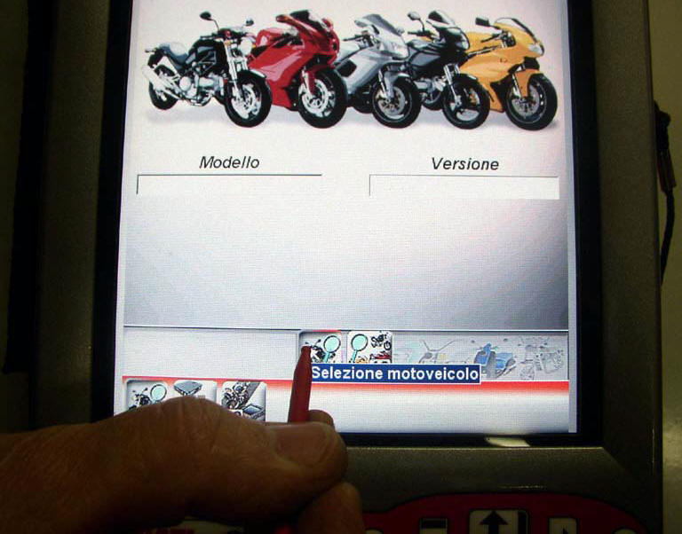
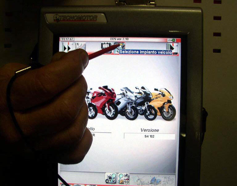
Press the "select vehicle" icon and, on the next screen, press the "select motorcycle" icon; select the motorcycle model and confirm, then select the version and confirm.
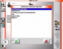
Press the icon "select system" to display a list of the bike’s systems that can be analysed.
Select one of the options shown in the following picture and press icon "confirm" (b) to confirm it.
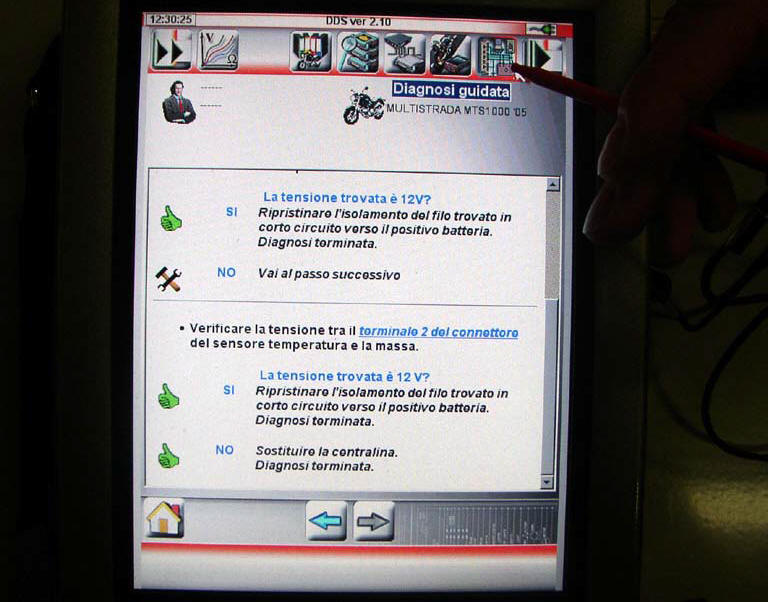
Press the "guided diagnosis" icon (c) to access the corresponding function.
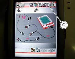
A series of screens are displayed indicating the operations required for correct diagnosis.
To determine whether the system has any internal problems, you can access the "self-diagnosis" function by pressing the corresponding icon. If any errors are present, the symbol (d) will be displayed. To determine the type of errors present, press the "errors" icon (e). Once errors are detected, it is possible to solve them using the step-by-step diagnosis; press "step-by-step diagnosis" icon (c).
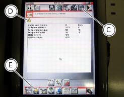
The dds diagnosis instrument will interrogate the electronic control unit and display the parameters analysed with their relative values.
 Fuel pressure test
Note
The on-screen icons used during this procedure are explained in a table at
the end of this section.
Undo the screws (2) and remove the flange cover (1).
Remove one of the two pipes o ...
 Testing the battery charging system
Note
The on-screen icons used during this procedure are explained in a table at
the end of this section.
You can determine the engine rpm required for generator to produce just
enough current to ...
Other materials:
Adjusting the front fork
The front fork used on this motorcycle has rebound, compression and spring
preload adjustment.
This adjustment is done using the outer adjusters:
Rebound damping;
Inner spring preload;
Compression damping.
Park the motorcycle in a stable position on its side stand.
Turn the adjust ...
Inputs and outputs of engine control unit and connection to can network
The diagram illustrates the inputs and outputs for the engine control unit.
The signals from the brake buttons, the exhaust
by-pass valve command signal and the gear sensor signal are transmitted over the
can line.
1I emergency engine cutout switch
2I start button
4I side stand button
6 ...
Electric system
Basic electric items are:
headlight:
low beam bulb type: 1xh7 blue vision (12v-55w);
high beam bulb type: 1xh1 (12v-55w);
parking light: led (12v-2.4W).
Electrical controls on handlebars.
Turn indicators:
front: led (13.5V-2.9W).
Horn.
Brake light switches.
Sealed battery, 12v-10 ...