
Ducati Diavel Service Manual: Air temperature sensor
Introduction
The engine control system on the diavel uses a sensor that measures air temperature. This sensor has a resistance of ntc type (negative temperature coefficient), that reduces its own value when the temperature increases. The air temperature sensor allows the engine control unit to modify the fuel-air mixture and ignition advance in relation to the atmospheric air temperature.
Components assembling position
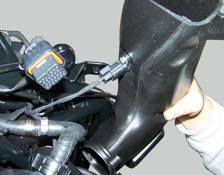
The air temperature sensor is mounted on the right hand air intake (the image also shows the location of the connection).
Wiring diagram
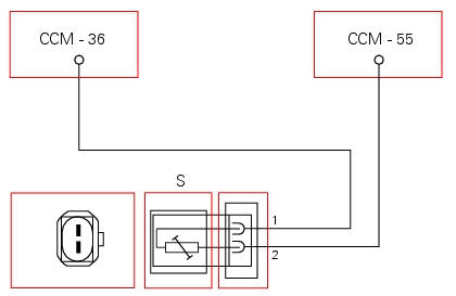
Ccm engine control connection, s air temperature sensor. 1 Green/blue - g/b, 2 black/purple - bk/v.
In the event of fault
In the event of an air temperature sensor fault, the engine control unit implements a recovery value of 25C.
Fault codes generated and possible correlated faults
Fault codes generated by the engine control unit and displayed by the dds (intake air temperature sensor diagnosis):
- Short circuit to vdc: check integrity of electric circuit and electrical connections.
- Short circuit to ground: check integrity of electric circuit and electrical connections.
- Open circuit: check integrity of electric circuit and electrical connections.
Note
Check integrity of electric circuit - short-circuit to vdc = with dashboard on, using a voltmeter, a voltage is measured between the wire tested and ground.
Check integrity of electric circuit - short-circuit to ground = with the battery cables disconnected, using an ohmmeter, continuity is detected between the wire tested and ground.
Check integrity of electric circuit - open circuit = with the battery cables disconnected, using an ohmmeter, no continuity is detected between the two ends of the wire tested.
The dashboard service display shows the error "air temperature" and the eobd warning light activates.
Possible correlated faults: inadequate engine power, irregular idle speed (target idle speed is 1350 rpm with engine stabilised at operating temperature), the engine does not start easily. Check: -sensor resistance, which must be approximately 2 kohm at 25 C.
The air temperature value may be checked using the dds. Check that the value given is plausible.
If none of the aforementioned tests identify the problem and the air temperature sensor is in proper working order, replace the engine control unit.
Component replacement methods
No special measures are necessary in order to replace the air temperature sensor.
 Component assembling position
The throttle valve position sensor is integrated in the throttle valve
actuator motor.
Location of electric connection for throttle valve actuator motor - tps
(throttle valve position sen ...
 Engine temperature sensor
Introduction
The engine control system on the diavel uses a sensor that measures the
temperature of the coolant (engine
temperature). This sensor has a resistance of ntc type (negative temperature ...
Other materials:
Legal rights
This warranty gives you specific legal rights, and you may
also have other rights which vary from state to state.
This warranty is in addition to the ducati limited
motorcycle warranty.
Additional information
Any replacement part that is equivalent in performance and
durability may be used in ...
Overhaul of the flywheel-alternator assembly
Examine the inner part of alternator rotor (24) for signs of damage. Check
that the starter clutch is working properly and
that the needle races do not show signs of wear or damage of any kind. If there
is any malfunction, remove the whole
assembly.
Disassembling the generator flywheel
U ...
Hands free system key-on and key-off
Key-on consists in turning on the hands free system and all
of its electronic devices.
Key-off consists in turning off the hands free system and all
electronic devices, and makes sure the engine is turned off.
Key-on is done using the button (6) on the handlebar on the
right switch or using ...