
Ducati Diavel Service Manual: Water radiators
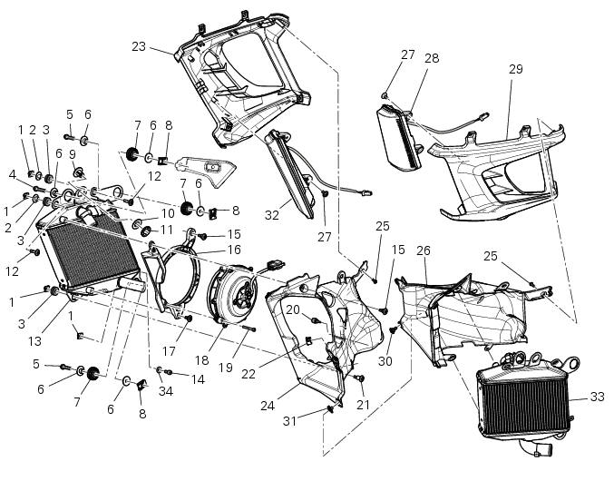
- Clip nut
- Spacer
- Vibration damper mount
- Screw
- Screw
- Spacer
- Vibration damper mount
- Clip nut
- Bush
- Spacer
- Rear sprocket
- Screw
- Water radiator (right)
- Screw
- Screw
- Air deflector (right)
- Special screw
- Electro-fan
- Screw
- Vibration damper mount
- Screw
- Plug
- Half-fairing (right)
- Internal air duct
- Screw
- Internal air duct
- Screw
- Front turn indicator
- Half-fairing (left)
- Special screw
- Clip nut
- Front turn indicator
- Water radiator (left)
- Washer
- Screw
Spare parts catalogue
Diavel abs radiator (right)
Diavel abs radiator (left)
Diavel abs half fairing
Diavel carbon abs radiator (right)
Diavel carbon abs radiator (left)
Diavel carbon abs half fairing
Important
Bold reference numbers in this section identify parts not shown in the figures alongside the text, but which can be found in the exploded view diagram.
The exploded view shows only the rh water radiator since the left one features the same components except the plug (22).
- Removing the water radiators
- Disassembling the water radiator unit
- Renewal of the cooling fan
- Reassembling the water radiator unit
- Refitting the radiator
 Refitting the cooling system hoses and unions
Position the pump/radiator sleeve (22) and the radiator/radiator sleeve (23).
Fit sleeve (23) and sleeve (22) to their corresponding fittings (n) and (o), and
bring them fully home on collars (p) ...
 Removing the water radiators
Loosen the screws (p) that retain the supports (s) of the front splashguard
to the air ducts (24) and (26).
Loosen the screws (30), to separate the two internal air ducts (24) and (26). ...
Other materials:
Checking brake pads for wear
Check brake pads wear through the inspection hole in the
callipers.
Change both pads if friction material thickness of even just
one pad is about 1 mm.
Warning
Friction material wear beyond this limit would lead to
metal support contact with the brake disc thus
compromising braking efficie ...
High beam lights not working
Fault codes
The hi beam light on the (slave) dashboard flashes at 1hz frequency.
Wiring diagram
Location of elements on motorcycle
(A) injection relay; (b) etv relay (throttle valve operating engine); (c)
radiator fan relay; (d) hands free relay.
Fuses located at the rear left of the ...
Removal of the gearchange control
Loosen and remove the pivot screw (4) securing the gearchange pedal (1) and
recover the washer (9) and the o-ring Seals (5).
Loosen and remove the screw (7) securing the gearchange lever (8) to the gear
selector shaft.
Withdraw the lever (8) complete with the gearchange control assem ...