
Ducati Diavel Owners Manual: Electric system
Basic electric items are: headlight: low beam bulb type: 1xh7 blue vision (12v-55w); high beam bulb type: 1xh1 (12v-55w); parking light: led (12v-2.4W).
Electrical controls on handlebars.
Turn indicators: front: led (13.5V-2.9W).
Horn.
Brake light switches.
Sealed battery, 12v-10 a.
Generator 12v-430w.
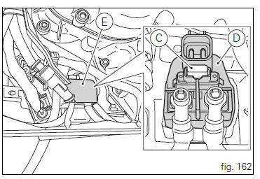
Master fuse, protected by a 30a fuse located on the solenoid starter, behind the battery (c, fig. 162).
Starter motor: 12v-0.7 Kw.
Tail light, brake light and rear turn indicators: parking: (13.5V-0.6W); stop: led (13.5V-2.8W); rear turn indicators: led (13.5V-2.06W).
Number plate light: led (13.5V-0.67W).
 Note
Note
See "replacing the high and low beam bulbs" on page 158 for relevant instructions.
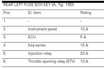
Fuses
There are twelve fuses that protect the electric components located inside the front and rear fuse boxes, and one on the electric solenoid starter. There is a spare fuse in every box.
Refer to the table below to identify the circuits protected by the various fuses and their ratings.
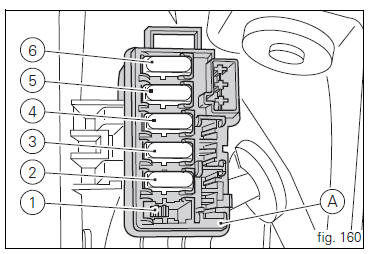
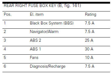
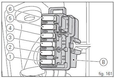
The rear left fuse box (a, fig. 160) And the rear right one (b, fig. 161) Are located under the seat, inside the underseat compartment.
To access the fuses, remove the seat (see "removal of the seat" on page 119).
To expose the fuses, lift the box protective cover. Mounting position and ampere capacity are marked on box cover.
 Note
Note
Remove the left cowling to reach the main fuse (see "charging the battery" on page 148).
The main fuse (c, fig. 162) Is positioned next to the battery, on the solenoid starter (d). Remove the fuse cap (e) to reach it.
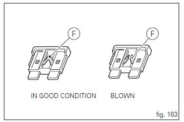
A blown fuse is identified by the interrupted centre link (f, fig. 163).
 Important
To prevent short circuits, replace the fuse after the key-off.
 Warning
Never use a fuse with a rating other than specified.
Failure to observe this rule may damage the electric system or even cause fire.
Injection /electric system diagram key
- Right-hand handlebar switch
- Immobilizer
- Hands free relay
- Hands free
- Front fuse box
- Right fan
- Left fan
- Fan relay
- Fuel pump relay
- Ride-by-wire relay (etv)
- Injection control unit (ems)
- Rear fuse box
- Data acquisition/diagnosis
- Starter motor
- Fused solenoid
- Battery
- Wiring ground
- Regulator
- Generator
- Fuel pump
- Fuel level
- Rear right turn indicator
- Rear light
- Rear left turn indicator
- Vehicle control unit (bbs)
- Antitheft alarm
- Exhaust valve starter motor
- Gear sensor
- Rear speed sensor
- Abs control unit
- Throttle twistgrip position sensor (aps)
- Starter motor - position sensor / ride-by-wire (tps/etv)
- Timing/rpm sensor
- Vertical map sensor
- Horizontal map sensor
- Engine temperature
- Air temperature sensor
- Vertical lambda sensor
- Horizontal lambda sensor
- Oil pressure switch
- Rear stop
- Side stand switch
- Clutch switch
- Front stop
- Main vertical injector
- Main horizontal injector
- Horizontal coil
- Vertical coil
- Left-hand handlebar switch
- Horn
- Front speed sensor
- Front left turn indicator
- Instrument panel on handlebar
- Instrument panel on tank
- Front right turn indicator
- Navigator
- High / low beam
- Parking light
Wire colour coding
B blue
W white
V violet
Bk black
Y yellow
R red
Lb light blue
Gr grey
G green
Bn brown
O orange
P pink
 Note
Note
The electric system wiring diagram is at the end of this manual.
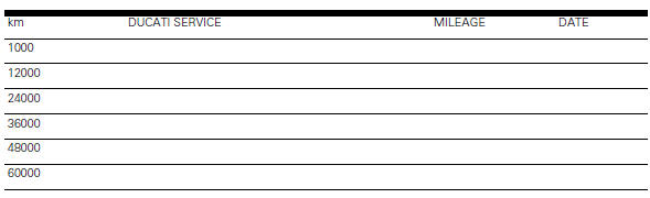
Scheduled maintenance reminder
 Colour schemes
Ducati red enamel code 54d234015 (akzo);
red frame and black rims.
Diamond black code 57e22714 (akzo);
enamel code 54m22705 (akzo);
clear lacquer part no. 228.880 (Ppg);
racing black frame blac ...

Other materials:
Spark plugs replacement
Check the colour of the ceramic insulation around the central electrode:
an even, light brown colour indicates the engine is in good condition and
running at the right temperature.
Inspect the centre electrode for wear and check spark plug gap, which should be:
0.8+/-0.1 Mm.
Important
...
Overall dimensions (mm)
Weights
Weight in running order without fluids and battery: 210 kg.
Carrying full load: 400 kg.
Warning
failure to observe weight limits could result in poor
handling and impair the performance of your motorcycle, and
you may lose control of the vehicle.
Important
Do not use addi ...
Fuel tank
fuel tank
Rubber pad
Spacer
Screw
Hose
Tray
Y-fitting
Hose
Hose
Filler cap
Screw
Complete hose guide
Screw
Hose clip
Hose
Screw
Screw
Sealing washer
Screw
Flange
Sealing washer
Spare parts catalogue
Diavel abs fuel tank
Diavel abs fuel system
Diav ...