
Ducati Diavel Service Manual: Injection relay
Introduction
The fuel pump, injectors and ignition coils are all powered via the injection relay. The relay also sends voltage to the engine control unit, which enables activation of the relay itself.
Component assembling position
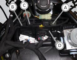
A injection relay; b etv relay (throttle valve actuator motor), c radiator fan relay, d engine control unit.
Connection wiring diagram
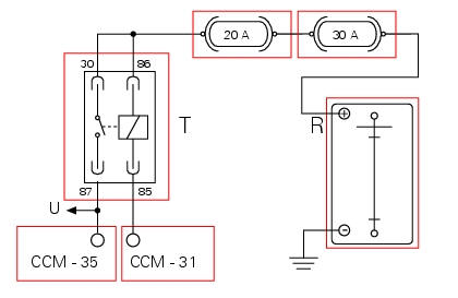
Ccm engine control connection, t injection relay. 85 Brown/black - bn/bk injection relay activation, 87 brown/white-bn/w ecu input voltage, u direct power to injectors, ignition coils and fuel pump, r battery power (+30), 30 and 86 brown - bn.
In the event of fault
In the event of an injection relay fault, the engine stops (if running) or will not start. The relay is not commanded by the ecu.
Fault codes generated and possible correlated faults
Fault codes generated by the engine control unit and displayed by the dds (fuel injection relay diagnosis):
- Open circuit: check integrity of fuses, electrical circuit and electrical connections.
- Short circuit to ground: check integrity of fuses, electrical circuit and electrical connections.
- Short circuit to vdc: check integrity of electric circuit and electrical connections.
Note
Check integrity of electric circuit - short-circuit to vdc = with dashboard on, using a voltmeter, a voltage is measured between the wire tested and ground.
Check integrity of electric circuit - short-circuit to ground = with the battery cables disconnected, using an ohmmeter, continuity is detected between the wire tested and ground.
Check integrity of electric circuit - open circuit = with the battery cables disconnected, using an ohmmeter, no continuity is detected between the two ends of the wire tested.
The dashboard service display shows the error "fuel injection" and the eobd warning light activates.
Possible correlated faults: the engine stops (if running) or will not start. Check:
- Integrity of fuses
- Relay function. After removing from its mounting, apply 12 v power to pin 85 and pin 86 of the relay and check that pin 87 and pin 30 close (continuity between pins)
Using the dds, activate the ignition coils, the fuel pump or the injectors. The injection relay is driven and its contacts (pin 87 and pin 30) should close.
If none of the aforementioned tests identify the problem and the relay is in proper working order, replace the engine control unit.
Component replacement methods
No special measures are necessary in order to replace the injection relay.
 Side stand button
Introduction
The side stand button is located on the side stand. Together with the signal
from the clutch button and the neutral signal
generated by the gear sensor (transmitted to the engine cont ...
 Throttle valve actuator motor relay
Introduction
The throttle valve actuator motor is powered by the engine control unit. The
engine control unit receives the necessary
power from a specific relay.
Component assembling position
...
Other materials:
Reassembly of the gearbox
To refit the gearbox components follow the procedure under sect. 9 - 9.2,
Reassembly of the crankcase halves, relating to
reassembly of the engine crankcase.
As a final practical test, ensure that with the gearbox in neutral the front
coupling dogs (a) of sliding gears (b) are
equidistant o ...
Clutch lever
Lever (1) disengages the clutch. It features a dial adjuster (2)
for lever distance from the twistgrip on handlebar.
The lever distance can be adjusted through 10 clicks of the
dial (2). Turn clockwise to increase lever distance from the
twistgrip. Turn the adjuster counter clockwise to decrea ...
Throttle valve position sensor
Introduction
The throttle valve position sensor (tps) of the diavel is mounted on the
throttle body.
The sensor is integrated into the throttle valve actuator motor, which
turns the spindle of the vertical cylinder throttle
valve directly.
The sensor sends information to the engine con ...