
Ducati Diavel Owners Manual: Warning indication (alarms/signals)
The instrument panel activates in real-time some warnings / malfunction that are not dangerous for the correct operation of the vehicle.
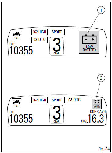
At key-on (at the end of the check) one or more "warnings" are displayed if they are active.
When a "warning" is triggered, the indication (amber yellow) remains well visible for 10 seconds (1, fig. 34) Then becomes smaller (2, fig. 34).
If there are multiple indicators, they will scroll automatically every 3 seconds.
 Note
Note
No signal lights turn on if one or more "warnings" are activated.
The following "warnings" could be displayed:
- "Low" battery level (low battery);
- Traction control "deactivated" (dtc off);
- Hands free key (hf) "not recognised";
- "Low " hands free key (hf) battery level;
- "High" engine coolant temperature (high temp);
- Steering release error - steering still locked (unlock error).
When one or more "warnings" are active, it is possible to go
to other functions by pushing button (2, fig. 14)
 h.
h.
 Indication of range reached for service
When service coupon threshold is achieved, upon every key-
on the system displays the indication of the type of
intervention that is required (oil service or desmo
service).
The (red) warning is ...
 Low battery level
The activation of this (amber yellow) "warning" indicates
that the status of the battery vehicle is low.
It is activated when the battery voltage is . 11.0 Volt.
Note
In this case, du ...
Other materials:
Indicator cons. Avg - average fuel consumption
This function indicates the "average" fuel consumption.
The calculation is made considering the quantity of fuel used and the km
travelled since the last trip 1 reset. When trip 1
is reset, the value is set to zero and the first available value is shown on the
display 10 seconds after the re ...
Indicator speed avg - average speed
This function shows the average speed of the motorcycle.
The calculation is made considering the distance and time travelled since the
last trip 1 reset. When trip 1 is reset, the
value is set to zero and the first available value is shown on the display 10
seconds after the reset. Dashes "- ...
Removal of the primary drive gear
Withdraw the clutch housing (1) complete with driven gear of the primary pair
(a).
Remove the inner spacer (2).
Remove the oil pump (d) (sect. 9 - 2.1, Removal of the oil pump).
Lock the primary pinion (b) with the holding tool 88713.3417 And loosen the
threaded ring nut (3) u ...