
Ducati Diavel Service Manual: Side stand button
Introduction
The side stand button is located on the side stand. Together with the signal from the clutch button and the neutral signal generated by the gear sensor (transmitted to the engine control unit over the can line), the side stand position signal is used to enable or disable engine start.
The following table indicates the only conditions in which starter motor
activation and, as a result, engine start, are
permitted: 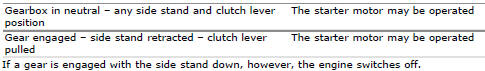
Component assembling position
The side stand button is integrated in the rotation pivot area of the side stand itself.
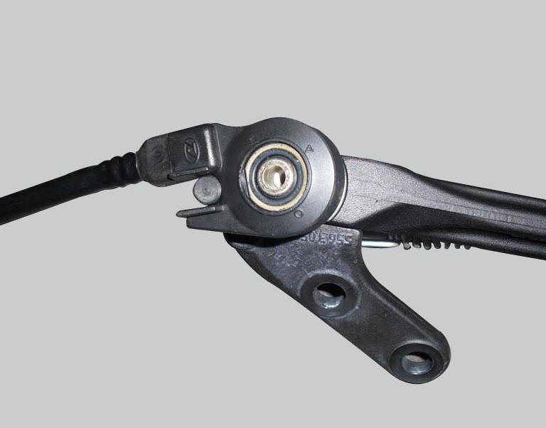
location of side stand connection.
Connection wiring diagram
Ccm engine control connection, s side stand button. 3 Black - bk, 2 white/black - w/bk.
In the event of fault
In the event of a side stand button fault, the safety conditions described in the introduction are not met.
Fault codes generated and possible correlated faults
The engine control unit generates no fault code in the event of a side stand button fault.
No errors are indicated on the dashboard.
- Integrity of electric circuit (open circuit, short-circuit to ground and toward vdc) and of the electrical connections
- Integrity of the side stand button. When the side stand is used (extended and retracted), the resistance on the button contacts (pin 2 and pin 3) must be zero in one position (continuity) and infinite in the other (open circuit)
Note
Check integrity of electric circuit - short-circuit to vdc = with dashboard on, using a voltmeter, a voltage is measured between the wire tested and ground.
Check integrity of electric circuit - short-circuit to ground = with the battery cables disconnected, using an ohmmeter, continuity is detected between the wire tested and ground.
Check integrity of electric circuit - open circuit = with the battery cables disconnected, using an ohmmeter, no continuity is detected between the two ends of the wire tested.
The dds instrument can be used to display the activation state of the side stand button.
If none of the aforementioned tests identify the problem and the side stand button is in proper working order, replace the engine control unit.
Component replacement methods
No special measures are necessary in order to replace the side stand button.
 Clutch lever button
Introduction
The clutch button is located on the clutch lever. Together with the signal
from the side stand button and the neutral signal
generated by the gear sensor (transmitted to the engine co ...
 Injection relay
Introduction
The fuel pump, injectors and ignition coils are all powered via the injection
relay. The relay also sends voltage to the
engine control unit, which enables activation of the relay its ...
Other materials:
Refitting the air filters
Apply universal sealant in the air duct (2) and (6) groove (d).
Fit seal (7) in the groove (d) having care to place it correctly in the relevant
seat so as to avoid abnormal wrinkles.
Pull out the filter cartridge (1) from the seat in the airbox.
Position the rh air duct (2).
Start ...
Check the idle and the co amount with warm engine
Start the engine;
Switch on the dds and check that it does not signal any error (otherwise
consult the relevant paragraph of this manual
to reset the error and proceed with the idle check);
Enter the "self diagnosis" menu by selecting the diavel model in the
available vehicle version. ...
Indication of range reached for service
When service coupon threshold is achieved, upon every key-on the system
displays the indication of the type of
intervention that is required (oil service or desmo service).
The (red) warning is activated as a large icon for 10 seconds upon every key-on
(1) then as a small warning that
remai ...