
Ducati Diavel Service Manual: Oxygen sensors
Introduction
An on-off type oxygen sensor (in normal operating conditions, the voltage generated by the sensors switches between a value close to 1v and a value close to 0v) is mounted on each of the exhaust manifold of the diavel.
Each oxygen sensor has its own internal heater, which receives 12v and has a ground connection controlled by the engine control unit with a pwm (pulse width modulation) signal.
Example of a pwm signal used by the engine control unit to control the oxygen sensor heater. While the signal period is constant, the duration of the part of the signal at 0v (ground) changes, varying the time during which the heater remains electrically powered (if the ground period is close to the signal period, the heater functions continuously, if the ground period is short, the heater functions in short intervals, whereas if the ground period is zero, the heater is not functional).
Component assembling position
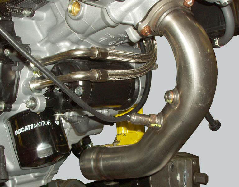
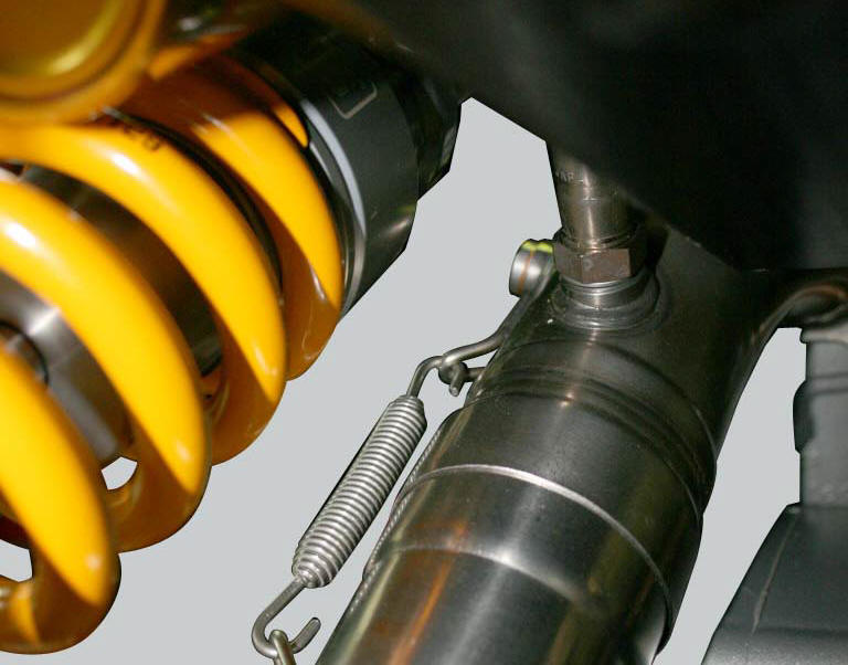
The two images show the oxygen sensor mounted on the exhaust manifold for the vertical cylinder and the sensor mounted on the exhaust manifold for the horizontal cylinder.
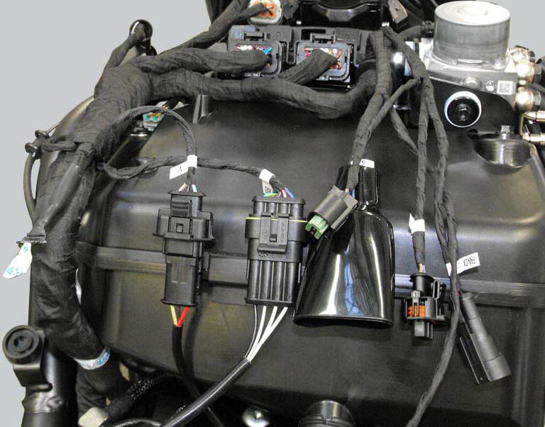
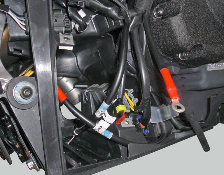
Location of vertical and horizontal cylinder oxygen sensor connections.
Connection wiring diagram
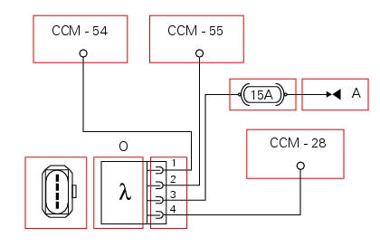
O horizontal cylinder oxygen sensor, ccm engine control connection. 1 Green/yellow - g/y and 2 black/purple - bk/v horizontal cylinder oxygen sensor signal input into ecu, 4 pwm signal for controlling horizontal cylinder oxygen sensor heater, light blue/yellow - lb/y, a key on positive (+15 from hands free relay 30) powering horizontal cylinder oxygen sensor heater.

V vertical cylinder oxygen sensor, ccm engine control connection. 1 Green/purple - g/v and 2 black/purple - bk/v vertical cylinder oxygen sensor signal input into ecu, 4 pwm signal for controlling vertical cylinder oxygen sensor heater, light blue/grey - lb/gr, a key on positive (+15 from hands free relay 30) powering vertical cylinder oxygen sensor heater.
In the event of fault
In the event of a fault of one or both oxygen sensors or their respective heaters:
- The engine control unit ceases to control the oxygen sensor heater
- The fuel system no longer functions in a closed loop (the engine control unit disables analysis of the signal received from the oxygen sensor and therefore functions in an open loop)
- Self-adaptive functionality is suspended (self-adaptive parameters not updated).
Fault codes generated and possible correlated faults
Fault codes generated by the engine control unit and displayed by the dds (vertical o2 sensor diagnosis - horizontal o2 sensor diagnosis - vertical o2 heater diagnosis - horizontal o2 heater diagnosis):
- Oxygen sensor for cylinder 1 - horizontal and/or oxygen sensor for cylinder 2 - vertical, open circuit: check integrity of electric circuit and electrical connections.
- Oxygen sensor for cylinder 1 - horizontal and/or oxygen sensor for cylinder 2 - vertical, short circuit to vdc: check integrity of electric circuit and electrical connections.
- Oxygen sensor for cylinder 1 - horizontal and/or oxygen sensor for cylinder 2 - vertical, short circuit to ground: check integrity of electric circuit and electrical connections.
- Oxygen sensor heater for cylinder 1 - horizontal and/or oxygen sensor heater for cylinder 2 - vertical, short circuit to ground: check integrity of fuse, electrical circuit and electrical connections.
- Oxygen sensor heater for cylinder 1 - horizontal and/or oxygen sensor heater for cylinder 2 - vertical, open circuit: check integrity of fuse, electrical circuit and electrical connections.
Note
Check integrity of electric circuit - short-circuit to vdc = with dashboard on, using a voltmeter, a voltage is measured between the wire tested and ground.
Check integrity of electric circuit - short-circuit to ground = with the battery cables disconnected, using an ohmmeter, continuity is detected between the wire tested and ground.
Check integrity of electric circuit - open circuit = with the battery cables disconnected, using an ohmmeter, no continuity is detected between the two ends of the wire tested.
The dashboard service display shows the error "lambda" (lambda sensor) and/or the error "lambda heater" (lambda sensor heater).
Possible correlated faults: power delivery uneven when exiting idle speed state, irregular idle speed (target idle speed is 1350 rpm with engine stabilised at operating temperature). Check:
- 15 A fuse.
- If power supply voltage (12 v - key on) is present on pin 3 of the lambda sensor (if not, consult sect. 6 - 7 "The hands free system).
- The seal integrity of the exhaust system upstream of the oxygen sensor installation location.
- If there is any air infiltration into the intake system (influences oxygen sensor function, bringing self-adaptive parameters to the permissible limits).
- Fuel pressure in fuel supply system (influences oxygen sensor function, bringing self-adaptive parameters to the permissible limits, see section fuel system circuit.
- Cylinder compression and valve clearance (influences oxygen sensor function, bringing self-adaptive parameters to the permissible limits)
If the dds displays the self-adaptive parameters, this indicates that the engine control system is operating in a closed loop with the oxygen sensors. The dds also displays the voltages generated by the oxygen sensors (which must oscillate On average between approximately 0.1 V and approximately 0.8 V). Note that the self-adaptive parameters should not approach the upper and lower extremes of this range as this would indicate that the fuel-air mixture is too rich or too lean.
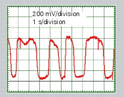
The graph shows the typical pattern for the voltage generated by the oxygen sensor with the engine at idle speed and at operating temperature. This voltage may be tested with an oscilloscope or even with a voltmeter, as it oscillates at low frequency.
If none of the aforementioned tests identify the problem and the oxygen sensors are in proper working order, contact ducati.
Component replacement methods
No special measures are necessary in order to replace the oxygen sensors. After replacing one or both of the oxygen sensors, reset the self-adaptive parameters relative to carburation with the dds.
 Absolute pressure sensors
Introduction
The engine control system of the diavel is equipped with two absolute
pressure sensors, with one connected to the intake
duct of each cylinder (map 1 cylinder 1 - horizontal - map 2 c ...

Other materials:
Electrical power for lighting and signalling devices
The front and rear running lights consist of led units with light conduits.
As a result, the light source is not visible as the
light is diffused through the surface of the light conduit.
These two images illustrate the front and rear running lights with light
conduits.
The figure ...
Riding style function (riding style change)
This function changes the motorcycle riding style.
Each riding style is associated with a different intervention level of the
traction control (dtc - ducati traction control) and
different engine power and output.
To change the motorcycle riding mode, press the reset button once
(3) and th ...
Headlight aim
The motorcycle must be perfectly upright with the tires inflated to the
correct pressure and with a rider seated, perfectly
perpendicular to the longitudinal axis.
Position the motorcycle 10 metres from a wall or a screen.
On the wall or surface, draw a horizontal line at the same height fr ...