
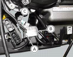
Ducati Diavel Service Manual: Location of elements on motorcycle
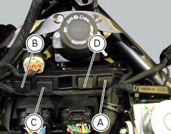
(A) injection relay; (b) etv relay (throttle valve operating engine); (c) radiator fan relay; (d) hands free relay.
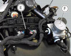
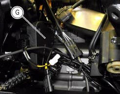
(E) ecu; (g) bbs (black box system or central electronics); (f) abs hydraulic unit with integrated control unit.
Fuses located at the rear left of the vehicle.
(1) 10A dashboard; (2) 5a engine control unit; (3) 15a key-sense; (4) 20a injection relay; (5) 15a throttle opening relay (etv).

Fuses located at the rear right of the vehicle.
(1) 7.5A black box system (bbs); (2) navigator; (3) 25a abs 2; (4) 30a abs 1; (5) 10a fans; (6) 7.5A
Diagnosis/recharge
(A) starter motor relay; (b) main fuse (30a).
The voltage regulator (c) is mounted on the electrical components support.
 Electrical power for lighting and signalling devices
The front and rear running lights consist of led units with light conduits.
As a result, the light source is not visible as the
light is diffused through the surface of the light conduit.
...

Other materials:
Refitting the brake disks
Before refitting the brake disc to the wheel, clean all contact surfaces
thoroughly and smear a medium strength
threadlocker on the threads of retaining screws (5).
Operating on the left side, fit the phonic wheel (6).
Tighten the fixing screws (5) of the brake disk (7) to the wheel followi ...
Adjusting the clutch lever and front brake lever
The clutch lever (1) is fitted with a span adjuster (2) which serves to alter
the distance of the lever from the handlebar.
The lever distance can be adjusted through 10 clicks of the dial (2). Turn
clockwise to increase lever distance. Turn the
adjuster counter clockwise to decrease lever d ...
Refitting the engine
Refitting is the reverse of removal.
Important
Apply recommended grease and tighten the special screws (6) to a torque of
60 nm +/- 5% (sect. 3 - 3, Frame torque
settings).
Tighten the nuts (3) to a torque of 48 nm +/- 5% (sect. 3 - 3, Frame torque
settings).
Warning
For the assembly seque ...