
Ducati Diavel Service Manual: Absolute pressure sensors
Introduction
The engine control system of the diavel is equipped with two absolute pressure sensors, with one connected to the intake duct of each cylinder (map 1 cylinder 1 - horizontal - map 2 cylinder 2 - vertical). They are used by the control unit to determine the quantity of fuel to be injected according to the speed-density strategy and to determine the atmospheric pressure (necessary information to correct the carburation in accordance with the altimetric measurement).
Components assembling position
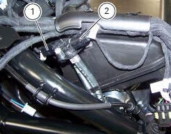
The absolute pressure sensors of the vertical (1) and horizontal (2) cylinders are fixed near the airbox (the image shows also the position of the sensor connection).
Wiring diagram
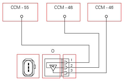
O absolute pressure sensor 1, horizontal cylinder. Ccm engine control connection, 1 ground, black/purple - bk/v, 2 power (5v), brown/purple - bn/v, 3 signal generated, green/white - g/w.
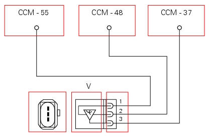
V absolute pressure sensor 2 vertical cylinder. Ccm engine control connection, 1 ground, black/purple - bk/v, 2 power (5v), brown/purple - bn/v, 3 signal generated, green/white - g/w.
In the event of fault
In the event of a fault of absolute pressure sensor 1, the engine control unit uses the information from absolute pressure sensor 2 instead.
In the event of a fault of absolute pressure sensor 2, the engine control unit uses the information from absolute pressure sensor 1 instead.
In the event of a fault of both absolute pressure sensor 1 and absolute pressure sensor 2:
- The engine control unit implements an atmospheric pressure value of 1.013 Bar.
- The fuel quantity injected is determined using the á-n strategy only.
Fault codes generated and possible correlated faults
Fault codes generated by the engine control unit and displayed by the dds (maps 1 sensor diagnosis - maps 2 sensor diagnosis):
- Absolute pressure sensor 1 (cylinder 1 - horizontal) and/or absolute pressure sensor 2 (cylinder 2 - vertical), open circuit: check integrity of electric circuit and electrical connections
- Absolute pressure sensor 1 (cylinder 1 - horizontal) and/or absolute pressure sensor 2 (cylinder 2 - vertical), short circuit to vdc: check integrity of electric circuit and electrical connections
- Absolute pressure sensor 1 (cylinder 1 - horizontal) and/or absolute pressure sensor 2 (cylinder 2 - vertical), short circuit to ground: check integrity of electric circuit and electrical connections
Note
Check integrity of electric circuit - short-circuit to vdc = with dashboard on, using a voltmeter, a voltage is measured between the wire tested and ground.
Check integrity of electric circuit - short-circuit to ground = with the battery cables disconnected, using an ohmmeter, continuity is detected between the wire tested and ground.
Check integrity of electric circuit - open circuit = with the battery cables disconnected, using an ohmmeter, no continuity is detected between the two ends of the wire tested.
The dashboard service display shows the error "pressure" and the eobd warning light activates.
Possible correlated faults: inadequate engine power, irregular idle speed (target idle speed is 1350 rpm with engine stabilised at operating temperature). Check:
- That the sensors are connected securely to the intake ducts and check the integrity of the pipe.
- That valve clearance is correct.
- Cylinder compression.
- That there is no anomalous air infiltration into the intake duct.
The dds may be used to read the absolute pressure value within the two intake ducts.
If none of the aforementioned tests identify the problem and the absolute pressure sensors are in proper working order, replace the engine control unit.
Component replacement methods
No special measures are necessary in order to replace absolute pressure sensor 1 and absolute pressure sensor 2, (check integrity of the rubber pipes via which they are connected to the two intake ducts). After replacing one or both of the pressure sensors, reset the self-adaptive parameters relative to carburation with the dds.
 Engine temperature sensor
Introduction
The engine control system on the diavel uses a sensor that measures the
temperature of the coolant (engine
temperature). This sensor has a resistance of ntc type (negative temperature ...
 Oxygen sensors
Introduction
An on-off type oxygen sensor (in normal operating conditions, the voltage
generated by the sensors switches between a
value close to 1v and a value close to 0v) is mounted on each of ...
Other materials:
Dtc (ducati traction control) setting function
This function allows you to customise the level of dtc intervention (ducati
traction control) or disable it for every riding
mode.
To access the function it is necessary to view the ""setting" menu", using
buttons (1) "s" or (2) "t" select the "riding
mode" function and press the reset butt ...
Refitting the airbox and throttle body
Position the filter box (1).
Operate on the vehicle lh side, connect connector (f) of the tps/div motor.
Operating on the right side of the vehicle, connect connector (e) from the
aps sensor.
Check for the vibration dampers (20) on the map sensor supporting bracket
(19).
Insert t ...
Overhauling the rear swingarm
Inside the swingarm (8), in correspondence with the pivot point on the frame,
there is a pair of ball bearings (10) and a
spacer (11) on the rh side, and a pair of roller bearings (6), with sealing
rings (5), on the lh side.
To change the bearings, proceed as follows.
Remove the shims ( ...