
Ducati Diavel Service Manual: Turn indicators not working
Fault codes
Dds: no fault code displayed.
Dashboard: no fault code displayed.
Wiring diagram
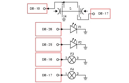
Db dashboard connection, bbs bbs unit connection, s turn indicator button, f1 front left turn indicator, f2 front right turn indicator, f3 rear left turn indicator, f4 rear right turn indicator. 2 On grey button - gr, 1 on red/blue button - r/b, 4 on black button - bk, db 26 white/black w/bk, db 25 green/black - g/bk, bbs 16 white/green - w/g, bbs 17 White/black w/bk.
Location of connections and components
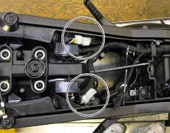
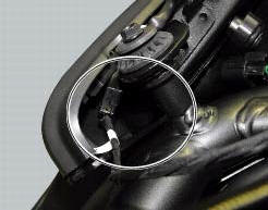
Location of rear turn indicator and number plate light connection.
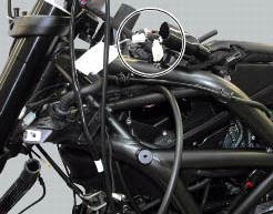
Location of left hand handlebar switchgear set connection.
Location of front right turn indicator connection.
Location of front left turn indicator connection.
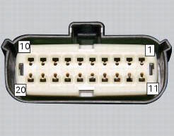
Pin numbering for wiring harness side dashboard connector.
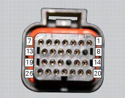
Pin numbering of wiring harness side bbs unit connection.
 Horn not working
Fault codes
Dds: horn diagnosis -> short circuit to ground (s.C. Gnd).
Dashboard: the error "claxon" (horn) is shown on the service display. The eobd
warning light activates.
Wiring diagram
...
 High beam flash not working - start/stop lap function not working
Fault codes
Dds: no fault code displayed.
Dashboard: no fault code displayed.
Wiring diagram
Db dashboard connection, s high beam flash button. 7 Orange - o, 1
red/blue - r/b.
Location of ...
Other materials:
Removing of the rear footrests
The removal of the rear footrests is described for the right side but it is
the same for both.
Undo the pin (13) and remove the rh rear footrest (12) from the frame.
Recover washer (8) and the o-rings (9).
If necessary remove the rubber footrest (11) of the footrest (12).
...
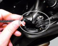
Removal of the throttle twistgrip
Peel back the rubber sleeve (a) protecting the throttle control cables.
Undo the screws (b) of the throttle grip (6) and open the command.
Disconnect the throttle grip cables (10) by unhooking the cable ends (c) from
their seats.
Remove the throttle twistgrip (6) from the handlebar.
...
Replacing the high and low beam bulbs
Before replacing a burnt-out bulb, make sure that the new
bulb complies with the voltage and wattage specified in the
"wiring diagram", page 179. Always test the new bulb
before refitting any parts you have removed.
Fig. 150 Shows the locations of the low beam bulbs (lo), high
beam ...