
Ducati Diavel Service Manual: Horn not working
Fault codes
Dds: horn diagnosis -> short circuit to ground (s.C. Gnd).
Dashboard: the error "claxon" (horn) is shown on the service display. The eobd warning light activates.
Wiring diagram
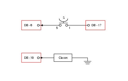
Db dashboard connection, s horn button. 5 Blue/white - b/w, 1 red/blue - r/b, db 19 purple/black - v/bk.
Location of connections and components
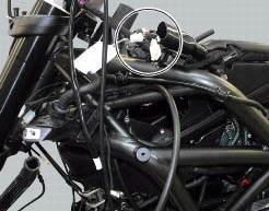
Location of left hand handlebar switchgear set connection.
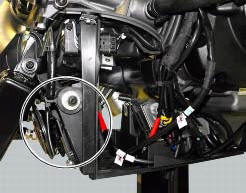
Location of horn with relative connection.
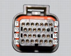
Pin numbering for wiring harness side dashboard connector.
Note
Check integrity of electric circuit - short-circuit to vdc = with dashboard on, using a voltmeter, a voltage is measured between the wire tested and ground.
Check integrity of electric circuit - short-circuit to ground = with the battery cables disconnected, using an ohmmeter, continuity is detected between the wire tested and ground.
Check integrity of electric circuit - open circuit = with the battery cables disconnected, using an ohmmeter, no continuity is detected between the two ends of the wire tested.
 Low beam lights not working
Location of connections and components
(A) injection relay; (b) etv relay (throttle valve operating engine); (c)
radiator fan relay; (d) hands free relay.
Fuses located at the rear left of ...
 Turn indicators not working
Fault codes
Dds: no fault code displayed.
Dashboard: no fault code displayed.
Wiring diagram
Db dashboard connection, bbs bbs unit connection, s turn indicator button, f1
front left turn i ...
Other materials:
Changing the engine oil and filter cartridge
Note
This operation has to be carried out with hot engine (but turned off)
because the oil in these conditions is more fluid and
its evacuation is faster and complete.
Remove the drain plug (3) with seal (a) from the oil sump and allow the oil
to drain off.
Warning
Dispose of oil and/or fil ...
Refitting the rear footrests
Note
The refitting of the rear footrests is described for the right side but it
is the same for both.
If previously removed, refit the rubber footrest (11) on the rear rh footrest
(6), by pushing it until pad (b) engages in the
other side.
Note
The rubber footrest (11) side featuring the le ...
Dashboard system
The vehicle is equipped with two dashboards: an lcd (1) located on the
handlebar containing the key indications (speed,
rpm, engine coolant temperature, and clock) and a tft colour display (2) located
in the tank fairing displaying trip
information (riding style set, odometer, consumption, ave ...