
Ducati Diavel Service Manual: Using a multimeter to check the electrical systems
Introduction
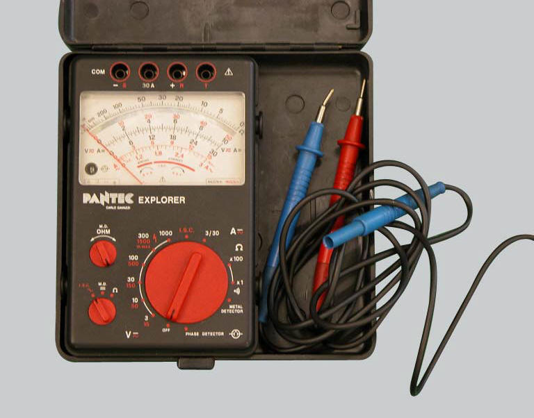
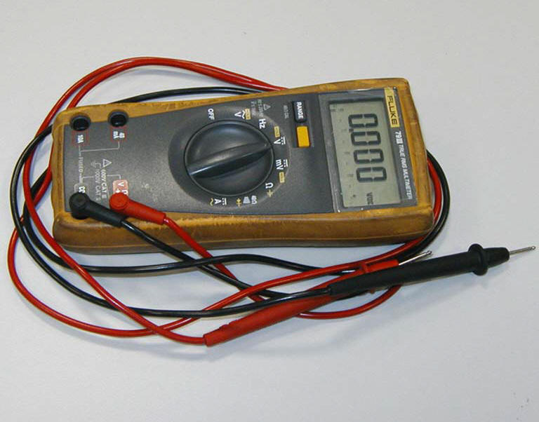
This instrument allows you to measure resistance, voltages, and current values. Multimeters can be divided into two basic types: analogue and digital display multimeter. An analogue multimeter has a pointer display. The dial is marked with the scales to be used for measurement of the various parameters. Digital units are equipped with a dial that displays numbers corresponding to the values of the measured parameters. The type of measurement to be carried out (voltage, current or resistance) is set by means of a selector or by means of several different sockets in which to insert the two test probe connector terminals. In certain cases it is essential to set the full scale value before proceeding. For example, in order to measure a 12 v signal, you need to set a full scale that is close to this value (e.G. 15 V or 20 v). It would be illogical to set a full scale value of 10 v; the same applies when setting current (amperes) or resistance (ohms). Sometimes the instrument can set the required full scale value automatically. Never exceed the maximum value allowed by the tester when measuring voltage or current signals.
Note
The dds diagnosis instrument (sect. 6 -13, Dds diagnosis instrument) can fulfil the function of digital multimeter.
Voltage measurement
Voltage measurements must be carried out by connecting the terminals of the tester in parallel to the load (e.G. To the wires feeding a light bulb or a relay, the two battery terminals, or the two wires supplying power to a control unit).
Voltages can be constant over time (dc voltage) or variable over time (ac voltage). In the first case, it is important to consider the negative and positive polarity of the application. It is therefore necessary to select on the multimeter the type of voltage you intend to measure. (Dc voltage is shown by the symbol = while ac voltage is denoted by ~).
current measurement
Current measurements must be made by connecting the multimeter terminals in series with the load (e.G. Disconnect one of the wires feeding power to a light bulb and connect one terminal of the multimeter to the free end of wire and the other terminal to the light bulb. When the lights switch is set to on, the bulb will illuminate normally and the tester will show the absorbed current, i.E. The amount of current passing through the wire. Warning: connections in series must be made and removed only when the power is switched off. Never attempt to make or break a series connection when a device is powered. Always make sure that the connection in series of the tester terminals on the electrical device is made is a safe manner in such a way that it cannot be broken accidentally.
Measurement of resistance values and electrical continuity
Resistance measurements must be taken only when the electrical device or section of the circuit is not powered and isolated from the main electric system (i.E. Not connected to the main electrical system). These measurements can be utilised to check the resistance value across several sensors. For example, after disconnecting the electrical wiring to the Rpm/ignition-injection system timing sensor (on the camshaft drive gear) the relative internal resistance can be checked by connecting a multimeter to its terminals. This makes it possible to check the electrical continuity of the winding inside the sensor (a reading of infinite resistance indicates that the winding is interrupted). Resistance measurement can also be used to check the continuity of sections of the electrical circuit or relay type switches. For example, to check the condition of a section of the electrical circuit between two connections, disconnect the connections and connect the terminals of the multimeter to the ends of the electrical cable in question to check that the specified resistance value is present. If this value is close to zero (i.E. Lower than approximately 0.3 Ohm) this means that the cable is not interrupted. Some instruments feature an audible signal that is emitted when the resistance approaches a value of zero. The same procedure must be adopted to check whether, for example, two contacts of a switch (relay or manual type) are making the contact correctly when closed. In this case the terminals of the multimeter must be connected to the switch terminals, checking that the resistance value is close to zero (or listening for the audible signal) when the switch is closed. To check that the multimeter is functioning correctly in "electrical continuity test" mode, short out the two test probes. The resistance value indicated must be almost nil and the audible signal must be activated.
Protections and precautions
The multimeter is equipped with protective fuses and batteries. These components must always be in perfect condition to ensure that the instrument is functioning correctly. When making electrical measurements always use the maximum caution to avoid short circuits, which can otherwise cause irreparable damage to the electric system and constitute a personal injury hazard. All maintenance work must be performed exclusively when the system is not live (disconnect the battery in advance). Never connect the multimeter in parallel to make current measurements, and never connect it in series to carry out voltage measurements.

 Description of the diagnosis instrument (dds)
The "dds" diagnostic system lets you diagnose any faults in the
injection-ignition system via a serial port. The system is
also equipped with functions to test various devices on the motorcycle. Th ...
Other materials:
Reporting of safety defects
If you believe that your vehicle has a defect which could
cause a crash or could cause injury or death, you should
immediately inform the national highway traffic safety
administration (nhtsa) in addition to notifying ducati north
america. If nhtsa receives similar complaints, it may open
an in ...
Removal of the front brake master cylinder
Warning
The brake master cylinder manufacturer advises against servicing the
brake master cylinder due to the safety critical
nature of this component. Incorrect overhaul of these critical safety components
can endanger rider and passenger safety.
Maintenance operations on these units are l ...
Gear indicator display on dashboard shows dashes, engaged gear not displayed
correctly, idle speed irregular
with gearbox in neutral
Fault codes
Dds: gear sensor diagnosis -> short circuit to ground or open circuit (s.C.
Gnd or c.O.) - Short circuit to vdc (s.C. Vdc)
- congruence (generic error - signal not correct).
Dashboard: the error "gear sensor" is shown on the service display. The eobd
warning light activates.
...