Ducati Diavel Service Manual: Abs diagnosis
Note
The on-screen icons used during this procedure are explained in a table at the end of this section.
If the abs system is not working correctly, system diagnosis is possible through the dds diagnosis instrument.
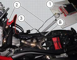
Turn on the dds diagnosis instrument (1) referring to the paragraph "tester power supply": use the power cord (2) part no. 97900.0230.
Connect the power supply cable (3) part no.97900.0227 Tot he power cord (2) part no. 97900.0230 And to the abs diagnosis connector (b) on the frame.

 Deactivating the service indication on the dashboard
The message "serv" is displayed on the dashboard, indicating that the
motorcycle should be serviced in accordance with
the programmed maintenance plan. This indication is activated after the first ...
 Icons table
...
Other materials:
Electrical components support
Clip
Screw
Voltage regulator
Battery fixing bracket
Battery support
Vibration damper mount
Hose clip
Vibration damper mount
Clip
Washer
Screw
Cover
Cable grommet
Battery
Battery mat
Screw
Bracket
Solenoid starter
Spring washer
Spacer
Screw
Horn
Scre ...
Abs fault indicator not working
Fault codes
Dds: displays a fault code described in the description of the abs system.
Dashboard: no fault code displayed.
Wiring diagram
Checks
The abs fault indicator indicates the occurrence of one or more faults in the
antilock brake system, or if the system itself
has been disable ...
Instrument panel on handlebar
Lcd.
Neutral light n (green). Illuminates when the gearbox is in neutral.
High beam light (blue).
It turns on to indicate that the high beam lights are on.
Engine oil pressure light
(red).
Illuminates when engine oil pressure is too low. It must turn
on at key-on, but ...