
Ducati Diavel Service Manual: Deactivating the service indication on the dashboard
The message "serv" is displayed on the dashboard, indicating that the motorcycle should be serviced in accordance with the programmed maintenance plan. This indication is activated after the first 1000 km and thereafter at intervals of 12000 km.
After the scheduled service has been carried out, the indication must be switched off as follows:
Note
The on-screen icons used during this procedure are explained in a table at the end of this section.
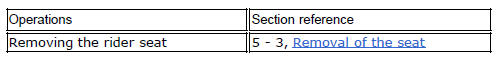
Turn on the dds diagnosis instrument (1) referring to the paragraph "tester power supply".
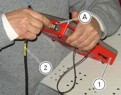
Connect the power and diagnosis cable (2) part no. 97900.0222 To the diagnosis connector (a) and the latter to the diagnosis socket (3) of the motorcycle.
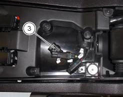
Enter the general functions menu, pressing "menu key 1" icon (b).
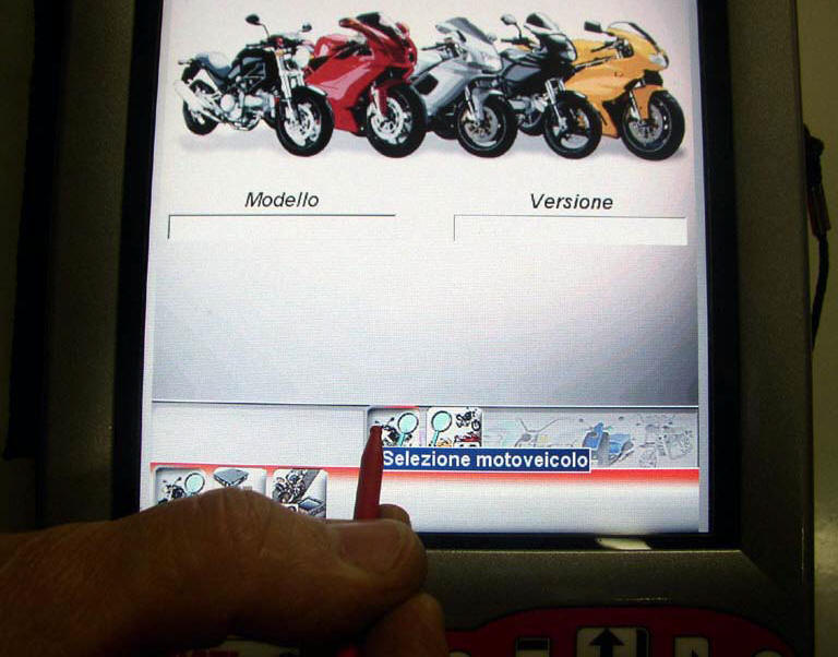
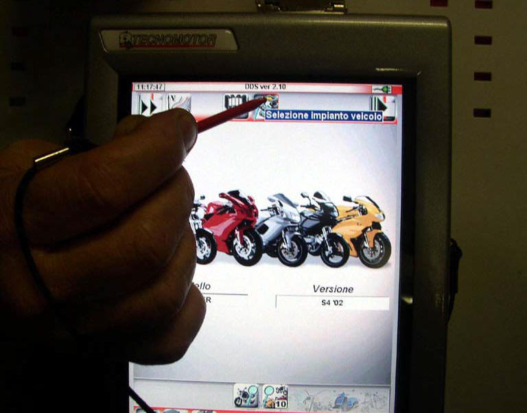
Press the "vehicle selection" icon and press "vehicle selection" icon in the following page; select the motorcycle model and confirm, then select the version and confirm.Press the "select system" icon.
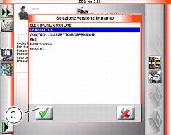
A list of the motorcycle’s systems that can be analysed will appear on the display.
Select the icon "dashboard".
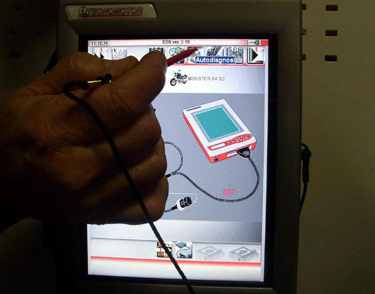
Press the "confirm" icon (c). Next, press the "self-diagnosis" icon to access the corresponding function.
The dds diagnosis instrument will interrogate the electronic control unit and display the parameters analysed with their relative values.
Press the "settings" icon to display the special parameters.
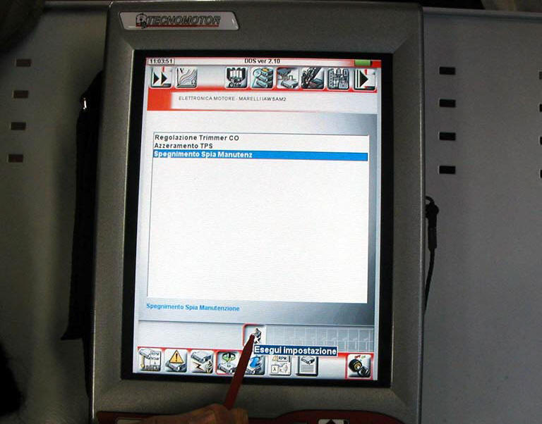
Select "service light off" and press "execute".
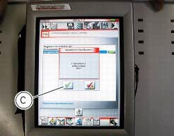
On completion of the operation, the message "was the operation completed successfully?" Will appear; press "confirm" (c).
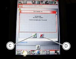
If any problems were encountered during the operation, the tester will display the relative error messages: you need to confirm or reject each message by pressing "confirm" (c) or "exit" (d), respectively.
Note
Once the "service" light has been reset with the dds diagnosis instrument, set the ignition switch to off and wait for at least 30 seconds before switching it on again.
 Testing the battery charging system
Note
The on-screen icons used during this procedure are explained in a table at
the end of this section.
You can determine the engine rpm required for generator to produce just
enough current to ...
 Abs diagnosis
Note
The on-screen icons used during this procedure are explained in a table at
the end of this section.
If the abs system is not working correctly, system diagnosis is possible
through the dds ...
Other materials:
Swingarm
Swingarm pivot
Washer
Special screw
Bush
Sealing ring
Roller bearing
Special screw
Rear swingarm
Spacer
Bearing
Spacer
Spacer
Hose clip
Pin
Chain slider (lower)
Washer
O-ring
Calliper mounting bracket
Circlip
Spacer
Inner ring
Hub
Cable grommet
Ch ...
Removing of the rear brake control
Warning
The brake master cylinder manufacturer advises against servicing the
brake master cylinder due to the safety critical
nature of this component.
Incorrect overhaul can endanger the rider and passenger.
Maintenance operations on these units are limited to renewal of the following
par ...
Removal of the tail light
Disconnect the connectors (a) and (b) of the tail lights (1) and (13).
Loosen the screws (4) and slide the tail lights (1) and (13) to the rear side;
recover the four spacers (3) and the washers
(14).
...