
Ducati Diavel Service Manual: Anti-pollution system and auto-adaptive strategy
Efficacy of the catalytic converter and oxygen sensors
To comply with current emissions legislation, the diavel is equipped with a trivalent catalytic converter, which oxidises co (carbon monoxide) and hc (unburnt hydrocarbons) and reduces nox (nitrogen oxides).
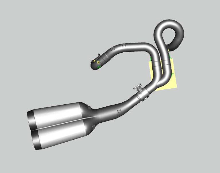
The image shows the exhaust system. The oxygen sensor for the horizontal cylinder (1) is visible on the right, the oxygen sensor for the vertical cylinder (2) is on the left. The catalytic converter is contained within the silencer, while the by-pass valve is installed in the section of pipe connecting the silencer to the twin tailpipes.
An oxygen sensor is mounted on the exhaust manifold for the vertical cylinder and on the exhaust manifold for the horizontal cylinder. The signal generated by these two sensors is processed by the engine control unit within the engine operating ranges included in the test cycle defined by emissions legislation (typically idle speed, the progression stage immediately above idle speed and low load conditions). By using these signals together with others from different sensors, the engine control unit generates a stoichiometric fuel-air mixture with the injectors (one part fuel for every 14.7 Parts of aspirated air). The exhaust gases produced by the combustion of this mixture can be treated extremely efficiently By the catalytic converter. This means that the catalytic converter reduces nox and oxidises co and hc by the maximum amount possible. If the engine and fuel system are functioning correctly, the signals generated by the oxygen sensors should oscillate between 0 v and 1 v in the engine operating ranges mentioned above:
- Lean fuel-air mixture -> high oxygen levels in exhaust gases -> oxygen sensor voltage approaching 0v.
- Rich fuel-air mixture -> low oxygen levels in exhaust gases -> oxygen sensor voltage approaching 1v.
therefore, on the basis of the signals received from the two oxygen sensor, the ecu continuously corrects the air-fuel mixture to keep it near the stoichiometric ratio, and the average electric signal generated by the two oxygen sensors is approximately 0.5 v. when the fuel system functions as described above, it is said to operating in a "closed loop". there are engine operating states in which the engine control system is in an "open loop", where the mixture is generated without processing the signals received from the two oxygen sensors. typically, these are:
- Warm-up
- Transitional states (acceleration and mild or severe deceleration - severe deceleration causes fuel cut-off).
- States resulting from lambda sensors fault.
- States not included in the test cycle defined by emissions legislation.
During acceleration or deceleration, where the mixture must be altered significantly by modifying the quantity of fuel injected, the oxygen sensor detects an excessive variation in oxygen levels in the exhaust gases, caused by the combustion of the altered mixture. If the engine control system were to operate in a closed loop in these conditions, the electric signal from the oxygen sensor would cause the fuel-air mixture to be corrected continuously, resulting in irregular engine function. For this reason, engine control switches to open loop operation during transitory acceleration or deceleration states. Therefore, when the engine is running at constant speed, engine control functions primarily in a closed loop, whereas in other conditions it functions primarily in an open loop.
The drawing illustrates the closed loop operation of the injection system.

The drawing illustrates the open loop operation of the injection system.
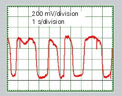
Typical pattern for the signal generated by the oxygen sensor within the engine operating ranges included in the test cycle defined by emissions legislation. The signal oscillates between 0 v and 1 v.
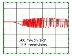
Typical pattern of the signal generated by the oxygen sensor during sensor heating stage (the operating temperature range for the sensor starts at approximately 300C).
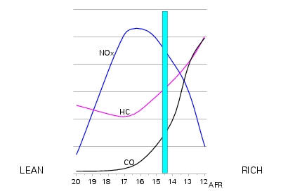
With fuel-air mixtures close to stoichiometric, the concentration of co, hc and nox contained in the exhaust gases is minimal. Untreated, however, these levels still exceed the limits permitted by emissions legislation. For this reason, the exhaust system includes a catalytic converter and two oxygen sensors, the latter ensuring optimum conditions for the efficiency of the catalytic converter.
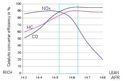
When passed through by exhaust gases produced by the combustion of a near-stoichiometric fuel-air mixture, the catalytic converter can reduce nox and oxidise co and hc with an efficiency approaching 100%.
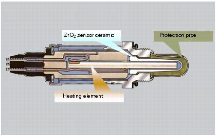
Operating principle of the zirconium dioxide (zro2) oxygen sensor
The external surface of the element in zirconium dioxide implemented in the two lambda sensors used on the diavel is in direct contact with the exhaust gases, while the internal surface is in contact with atmospheric air. Both surfaces are coated with a thin layer of platinum, which becomes electrically charged as a result of the difference in oxygen concentration between the two parts of the sensor (the part exposed to atmospheric air and the part in contact with exhaust gases), generating a voltage. This voltage may assume values within the following range:
- Combustion with lean mixture -> high oxygen levels in exhaust gases -> oxygen sensor voltage is low (approaching 0 v)
- Combustion with rich mixture -> low oxygen levels in exhaust gases -> oxygen sensor voltage is high (approaching 1 v)
This electrical signal is transmitted to the ecu via the sensor output connection. The oxygen sensor only starts functioning correctly at temperatures of at least 300C. At these temperatures, the zirconium dioxide element becomes permeable to oxygen ions, meaning that it can be crossed by the ions themselves, generating a difference in potential between the two platinum surfaces. To reach operating temperature more rapidly, there is an electric heating element inside the sensor itself, which receives 12v power and has a ground connection controlled by the ecu in pwm (pulse width modulation) mode. The pwm percentage is modified by the ecu in relation to engine temperature, to heat the oxygen sensor to operating temperature rapidly after a cold start. Heater element control is disabled in key on state with the engine off and during starting (ecu does not provide connection to ground in these conditions).
To allow the oxygen sensor to reach operating temperature rapidly, a heating element is included within its housing, which receives 12 v power and has a ground connection controlled as required by the ecu. The signal generated by the sensor switches from a voltage close to 1v to a voltage approaching 0v when the fuel-air mixture reaches a nearstoichiometric ratio (air-fuel ratio of 14.7).
Operating principle of the catalytic converter
The catalytic converter consists of a monolith metallic core with a honeycomb structure. It therefore has hundreds of small channels, which are covered with a layer of aluminium oxide washcoat. The exhaust gases are passed through this honeycomb structure. The catalyst substances (noble metals), such as platinum, rhodium and palladium, with which the products of combustion come into contact, are deposited on the washcoat layer. The principle reactions taking place in a three-way catalytic converter oxidising co and hc and reducing nox are as follows:
- Co reacts with oxygen to produce water (h2o) and carbon dioxide (co2)
- Hc compounds react with oxygen to produce water (h2o) and carbon dioxide (co2)
- Nox compounds react with co to produce nitrogen (n2) and carbon dioxide (co2)
These reactions only begin to develop once the catalytic converter reaches a temperature of at least approximately 300C.
This exhaust post-treatment device does not have an unlimited lifespan, and its effectiveness is reduced with increasing mileage. The lifespan of the catalytic converter is significantly reduced if it comes into contact with high quantities of unburnt fuel. As a result, never attempt to push-start the motorcycle if starting is impeded by a mechanical or electrical fault. Furthermore, the ignition system must always be in perfect working order. Only use engine oil specified by ducati, as it has a low ash content (ash obstructs the tiny catalytic converter channels over time).

The image shows a monolith core in excellent condition.

The image shows a monolith core that has deteriorated as a result of using engine oil not recommended by ducati.
Self-adaptive parameters
Within the engine operating ranges included in the test cycle defined by emissions legislation, the ecu corrects the fuelair mixture to maintain the average signals received from the oxygen sensors close to a value of approximately 0.5 V.
This ensures that the combustion process produces exhaust gases that can be treated highly efficiently by the catalytic converter. Obviously, fuel-air mixture correction capability of the ecu is limited. As a result, a number of self-adaptive parameters are used in the ecu software, which modify the base maps for the quantity of fuel injected. These parameters make it possible to exploit the full mixture correction range and, therefore, to recover from deviations from the desired average value for the oxygen sensor signals of approximately 0.5 V. These deviations may be due to the following causes:
- Ageing of the components of the cylinder unit, resulting in deviation from rated specifications (valve clearance, encrustation in combustion chamber and on valves, cylinder-piston seal integrity, variations in intake and exhaust gas flow)
- Ageing of the elements of the engine control system (variations in electrical characteristics of sensors and actuators)
- Fault of one or more elements influencing the combustion process or mixture production process (such as induction anomalies, injector malfunction, non-conforming fuel pressure etc.)
The ecu defines specific self-adaptive parameters for each cylinder correlated to ten different functional zones of the engine. There are two separate auto-adaptive parameters - denominated "long term" and "real time" - for each zone and for each cylinder.
- When the engine is switched off, the ecu remains powered for a predetermined number of seconds (power latch or selfshut down function), during which the real time self-adaptive parameters are memorised in the ecu, updating the long term parameters.
- When the engine is switched on, the ecu retrieves the long term parameters from its memory and uses them, updating them continuously. These therefore become the real time parameters.
Reading the self-adaptive parameters with the dds diagnostic instrument makes it possible to ascertain whether the two cylinder units of the engine are functioning correctly (the dds displays the self-adaptive parameters only when engine control is in a closed loop with the oxygen sensors). In the event of malfunction, these parameters approach one of the two limits defining their range of possible values (the ecu is continuously correcting the base maps). In this case, the following is necessary:
- Identify and rectify the fault
- Reset the self-adaptive parameters with the dds
- Ride the motorcycle normally or simply leave running at idle speed, to allow the ecu to recalculate the new self-adaptive parameters
 Explanation of the function of the ride-by-wire system
Mechanism
Via metal cables, the throttle grip operates a roller mounted on one end of a
spindle located near the horizontal cylinder
throttle valve spindle.
The aps sensor, which measures the p ...
 Ignition coils
Introduction
The engine control system of the diavel includes two ignition coils: one for
the horizontal cylinder and one for the vertical
cylinder. These coils are installed directly in the spark ...
Other materials:
Refitting the timing gears
Before reassembling the removed parts, check timing gears (13) for wear.
Change, if necessary.
Important
The timing gears (13) must always be renewed as a pair.
Refitting is the reverse of removal.
Warning
When introducing the driven gear (b) check that the tongue (15) is
correctly fitted o ...
Braking
Slow down in time, shift down to engine-brake first and then
brake applying both brakes. Pull the clutch lever before
stopping the motorcycle, to avoid sudden engine stop.
Abs system
Using the brakes correctly under adverse conditions is the
hardest – and yet the most critical - skill to mast ...
Turn indicators not working
Fault codes
Dds: no fault code displayed.
Dashboard: no fault code displayed.
Wiring diagram
Db dashboard connection, bbs bbs unit connection, s turn indicator button, f1
front left turn indicator, f2 front right
turn indicator, f3 rear left turn indicator, f4 rear right turn indicator. ...