
Ducati Diavel Service Manual: Clock setting function
This function sets the clock.
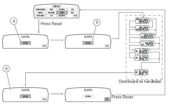
To access the function it is necessary to view the ""setting" menu", using buttons (1) "s" or (2) "t" select the "clock" function and press the reset button (3) to confirm.
In the following screen the message "setting" is highlighted in green (4); now, press the reset button (3) for 3 seconds to edit the time displayed on the handlebar dashboard, and the "setting" indication highlighting becomes grey (5).
Clock setting
On entering this mode, the message "am" will flash; press button (2) "t", the message "pm" starts flashing; press button (2) "t" to return to the previous step (if the current time is 00:00, 12:00 will be displayed when switching from "am" to "pm"); press button (1) "s" to access the hour setting mode; the hour value starts to flash; each time button (2) "t" is pressed increases the digit by 1 hour; pressing and holding button (2) "t", the digit increases by 1 hour every second (the hour value does not flash while the button is kept pressed).
Pressing button (1) "s" gives access to the minute setting mode; minutes start to flash.
Each time button (2) "t" is pressed increases the digit by 1 minute; pressing and holding button (2) "t", the digit increases by 1 minute each second; pressing and holding the button (2) "t" for more than 5 seconds, the value increases by 1 every 100 m (the second value does not flash while button (2) "t" is kept pressed).
If you press button (1) "s" setting is completed and the tank dashboard display "setting" item is again highlighted in green (6).
To exit, select "exit" and press the reset button (3).
Note
In case of a battery is cutoff, when the voltage is restored and at the next key-on, the clock is always reset (it starts automatically from 00:00).
 Battery voltage indicator (battery)
This function describes the battery voltage indicator.
To access the function it is necessary to view the ""setting" menu", using
buttons (1) "s" or (2) "t" select the "battery"
function and pre ...
 Units of measurement modification function
This function allows you to change the units of measurement of the displayed
values.
To access the function it is necessary to view the ""setting" menu", using
buttons (1) "s" or (2) "t" to sel ...
Other materials:
Checking drive chain tension
Important
Have chain tension adjusted by a ducati dealer or
authorised service centre.
Make the rear wheel turn until you find the position where
chain is tightest.
Set the vehicle on the side stand. Push down the chain at the
point of measurement and release.
Measure the distance betwee ...
Changing the coolant
Warning
This operation must only be carried out when the engine is cold.
Attempting to change the coolant with the engine hot
could lead to burns from hot coolant or scalding steam.
Place a container under the engine and place the motorcycle on its side
stand.
Remove the expansion reserv ...
Removal of the gearchange control
Loosen and remove the pivot screw (4) securing the gearchange pedal (1) and
recover the washer (9) and the o-ring Seals (5).
Loosen and remove the screw (7) securing the gearchange lever (8) to the gear
selector shaft.
Withdraw the lever (8) complete with the gearchange control assem ...