
Ducati Diavel Service Manual: Dashboard diagnosis
This function identifies any abnormal vehicle behaviours.
The dashboard activates any abnormal vehicle behaviours in real time (errors).
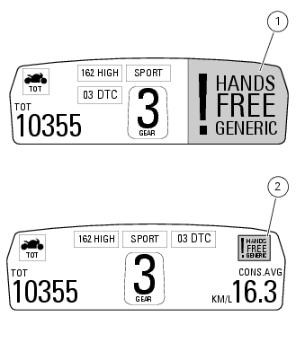
At key-on (at the end of the check) one or more "errors" are displayed in red (only if they are active).
When an "error" is triggered, the indication (red) remains well visible (1) for 10 seconds then becomes smaller (2).
If there are multiple errors, they will scroll automatically every 3 seconds. The "engine/vehicle diagnosis - eobd" light on dashboard located on handlebar always turns on when one or more errors are activated.
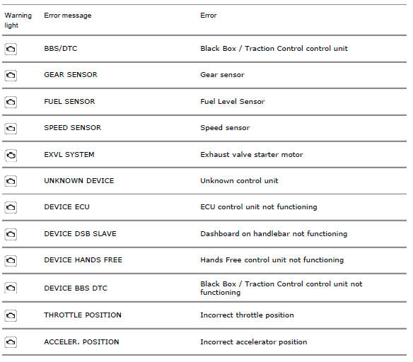
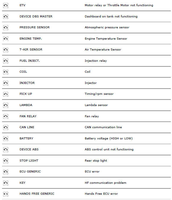
The table below shows the errors that can be displayed.
 Steering release error - steering still locked
The activation of this (amber yellow) "warning" indicates that the hands free
system was not able to extract the steering
lock.
Note
In this case, we recommend switching the vehicle off and on (k ...
 Setting menu
This menu is used to enable/disable and set some motorcycle functions.
To access the "setting menu" press and hold button (2) "t" for 3 seconds.
Note
When within this menu no other function can b ...
Other materials:
Abs diagnosis
Note
The on-screen icons used during this procedure are explained in a table at
the end of this section.
If the abs system is not working correctly, system diagnosis is possible
through the dds diagnosis instrument.
Turn on the dds diagnosis instrument (1) referring to the paragraph "tester ...
Adjusting the front fork
The front fork used on this motorcycle has rebound,
compression and spring preload adjustment.
The settings are adjusted using external adjuster screws.
To adjust rebound damping (fig. 109);
To adjust spring preload (fig. 109);
To adjust compression damping (fig. 110).
Park the mo ...
Refitting the seat
Note
Apply recommended grease to the hole (a) of latch (6).
Fit the seat (1) as follows: insert the tabs (b) (on the front side) under
the rubber pads (c) of the gloves compartment;
then push the seat rear side until hearing the lock latch click.
...