
Ducati Diavel Service Manual: Setting menu
This menu is used to enable/disable and set some motorcycle functions.
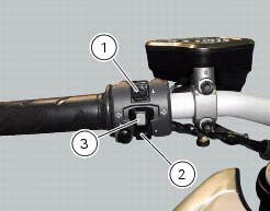
To access the "setting menu" press and hold button (2) "t" for 3 seconds.
Note
When within this menu no other function can be displayed.
Important
For safety reasons, the setting menu can only be accessed when motorcycle speed is lower than or equal to 20 km/h. If this menu is open and the speed of the motorcycle exceeds 20 km/h, the dashboard automatically exits the menu and returns to the "main" display.
The setting menu contains the following "items":
- Riding mode
- Menu 2
- Back light
- Rpm
- Pin code
- Lap
- Battery
- Clock
- Set units
- Abs
- Exit
To quit the setting menu, use button (1) "s" or button (2) "t" to select the "exit" indication and press the reset button (3).
 Dashboard diagnosis
This function identifies any abnormal vehicle behaviours.
The dashboard activates any abnormal vehicle behaviours in real time (errors).
At key-on (at the end of the check) one or more "errors" ...
 Riding mode customisation
This function customises each riding style.
To access the function it is necessary to view the ""setting" menu", using
buttons (1) "s" or (2) "t" select the "riding
mode" function and press the ...
Other materials:
Tips for use on the track
We recommend level 8 be used for a couple of full laps (to
allow the tyres to warm up) in order to get used to the
system. Then try levels 7, 6, etc., In succession until you
identify the dtc intervention level that suits you best (always
try each level for at least two laps to allow the tyres t ...
Refitting the external components
Fit the cap (39) on spring (38) until it engages.
Mount ball (40), spring (38) with cap (39), washer (37) and screw (36) on the
chain side half-casing by starting the
screw into hole (f).
Note
The spring (38), with cap (39), must be oriented as shown.
Tighten the screw fully home to a torqu ...
Refitting the gearchange mechanism
Make sure that the gearchange linkage assembly (6) is installed with the ball
joint with a left-hand thread (a) facing the
lever (8).
Apply the recommended grease to the non-threaded surface of the pin (4).
Fit the first o-ring (5) in the pin (4).
Start the pin (4) in the gearchange leve ...