
Ducati Diavel Service Manual: Description of the diagnosis instrument (dds)
The "dds" diagnostic system lets you diagnose any faults in the injection-ignition system via a serial port. The system is also equipped with functions to test various devices on the motorcycle. The dds diagnosis instrument can be used to measure current and voltage on any electrical device, to perform tests on individual components and to measure pressure and temperature values.
The dds (1) part number 97900.0215 Consists of a palmtop display (a), a bbad self-diagnosis module (b) and a display memory card (c).
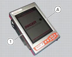
The touch-screen display unit (a) serves for both data display and input, using the stylus housed on the side of the unit.
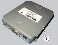
The self-diagnosis module (b) enables communication between the dds diagnosis instrument (1) and the motorcycle’s on-board electronic control unit (ecu).
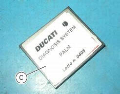
The user interface software resides in the display memory card (c) which is housed in the palmtop display unit (a).
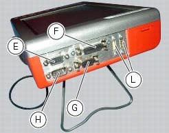
The display unit is equipped with two connection panels: one at the top of the instrument and one at the bottom.
The top connection panel has 6 connection sockets with the following functions:
- One vga output (e);
- One port for connection of the measurement module (f);
- One rs232 serial port for connection of peripheral devices (com1) (g);
- A second rs232 serial port for connection of peripheral devices (com2) (h);
- Two generic usb ports (usb1 and usb2) (l).
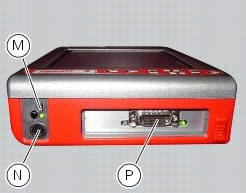
The bottom connection panel has 3 connection sockets with the following functions:
- One usb port (m);
- One power connection socket (n);
- One diagnostics connection socket (p).
You can connect a printer to the dds diagnosis instrument (1) to print test reports: connect the printer to the serial port (com1) (g) located on the top connection panel of the tester (1).
Technical data
Power supply:
- From the mains - 220 v;
- From the vehicle battery - 12 v.
Components supplied with the dds diagnosis instrument
The dds diagnosis instrument (1) is supplied in a kit together with the following items:
- Rechargeable dds battery
- Battery charger
- Mains power adapter
- Usb memory card reader
- Power and diagnostic cable complete with fuse
- Cd containing dds installation software for pc
- Usb cable
- Belt tension sensor
 Using a multimeter to check the electrical systems
Introduction
This instrument allows you to measure resistance, voltages, and current
values. Multimeters can be divided into two basic
types: analogue and digital display multimeter. An analogue m ...
 Tester power supply
The dds (1) part number 97900.0215 Can be powered from the vehicle as
follows:
From the mains power supply: by connecting the power supply connector
(n) to the network power supply (2) pa ...
Other materials:
Refitting the crankshaft/connecting rod assembly
Install the connecting rod assembly (6) and (2) in the crankcase, carry out
the shimming and crankcase half reassembly
procedure as described in sect. 9 - 9.2, Reassembly of the crankcase halves.
Important
Make sure that the connecting rods (2) are correctly positioned in the
cylinders. Incor ...
Tail light - number plate holder
Rh tail light
Vibration damper mount
Spacer
Screw
Number plate light
Screw
Screw
Plate
Number plate holder
Nut
Screw
Rear chain guard
Lh tail light
Spring washer
Vibration damper mount
Splashguard
Screw
Spacer
Screw
Washer
Splashguard (europe - australi ...
Indicator trip time - trip time
This function shows the vehicle trip time.
The calculation is made considering the time travelled since the last trip 1
reset. When trip 1 is reset, the value is set to
zero.
The active phase calculation occurs when the engine is running and the vehicle
is stopped (when the vehicle is not ...