
Ducati Diavel Service Manual: Filling the clutch circuit
Warning
Clutch fluid will damage painted surfaces if spilled on them. It is also very harmful if it comes into contact with the skin or with the eyes; in the case of accidental contact, wash the affected area thoroughly with plenty of running water.
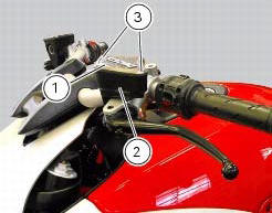
Remove cover (1) and membrane from the clutch fluid reservoir (2) by loosening the screws (3).

Fill the tank with specified oil (sect. 3 - 2, Fuel, lubricants and other fluids) taken from an intact container.
Important
During the following operation, the fluid level must remain topped up at all times. The end of the transparent plastic tubing must remain immersed in the discharged fluid at all times.
Operate the clutch lever and keep it pulled to fill the circuit and expel any air.
Connect the bleed tool to the bleed valve (4).
Note
Follow the manufacturer's instructions when using a commercial clutch bleeding tool.
Loosen the bleed valve (4) and pump with the bleeder. Make sure that the reservoir level does not fall below the min mark.
Repeat the bleeding operation until the fluid flowing from the tube is completely free of air bubbles.
If you do not have a bleeding tool available, connect a length of transparent plastic tubing to the bleed valve (4) as outlined in the draining procedure.
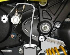
Open the bleed valve by 1/4 turn and operate the clutch lever several times until the fluid flows out of the bleed valve (4).
Pull the lever fully in and then loosen the bleed valve by at least a 1/4 turn.
Wait for a few seconds; then release the lever gradually while simultaneously closing the bleed valve (4).
Important
Do not release the clutch lever until the bleed valve has been fully tightened.
Repeat the bleeding operation until the fluid emerging from the plastic tube is free of air bubbles.
Close to a torque of 4 nm +/- 10% (sect. 3 - 3, Frame torque settings) the bleed valve (4) and install the protection cover.
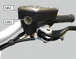
Top up the fluid level to approximately 3 mm above the min mark of the tank.
Reassemble cover (1) and membrane from the clutch fluid reservoir (2) by tightening the screws (3).
 Draining the clutch hydraulic circuit
Warning
Clutch fluid will damage painted surfaces if spilled on them. It is
also very harmful if it comes into contact with the skin or
with the eyes; in the case of accidental contact, wash the a ...
 Adjusting the steering head bearings
Excessive handlebar play or shaking forks in the steering head indicate that
the play in the steering head bearings
requires adjustment. Proceed as follows:
loosen the clamp screw (1) that holds t ...
Other materials:
Removing the water radiators
Loosen the screws (p) that retain the supports (s) of the front splashguard
to the air ducts (24) and (26).
Loosen the screws (30), to separate the two internal air ducts (24) and (26).
Disconnect the wiring connectors of the main wiring loom (c) from both fans.
Disconne ...
Replacing the rear phonic wheel sensor
Disconnect the rear abs sensor (5) connector (c) from the main electric
wiring.
Open all the retainer clamps of the rear abs sensor cable (5): refer to table of
sect. 7 - 6, Flexible wiring/hoses
positioning.
Remove the rear abs sensor (5) from its seat on the rear calliper mounting ...
Primary drive gears
Clutch drum/primary drive gears
Spacer
Threaded ring nut
Lock washer
Spare parts catalogue
Diavel abs clutch
Diavel abs connecting rods
Diavel carbon
abs
clutch
Diavel carbon
abs
connecting rods
Important
Bold reference numbers in this section identify parts not shown in th ...