
Ducati Diavel Service Manual: Reassembly of belly fairing
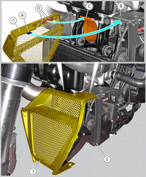
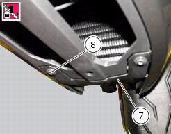
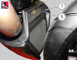
Position the oil cooler shield (7) inserting the tab (a) into the slit (b) in the electrical components support (s).
Note
On refitting, make sure that the tab (c) remains positioned under the retainers (d) of the shield (7).
Fit clips (11) on bracket (13) and orient them as shown in the figure.
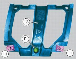
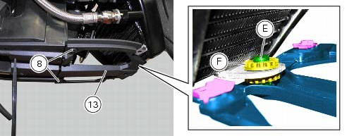
Apply rubber lubricant to the pin (e) of the bracket (13).
Insert pin (e) in the vibration damping pad (f) of the oil cooler.
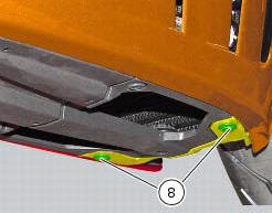
Fit the bracket (13) on the electrical components support, and tighten the screws (8) to a torque of 4 nm +/- 10 % (sect. 3 - 3, Frame torque settings).
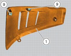
Fit clips (9) on lh belly fairing (2) and orient them as shown in the figure.
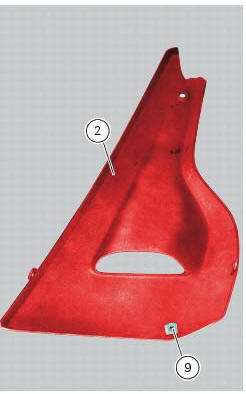
Put the lh belly fairing (2) in position by engaging slot (e) in the electrical components support, as shown in the figure.
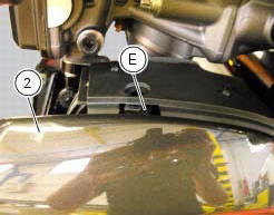
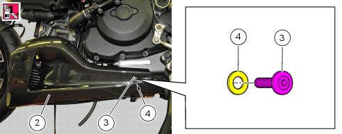
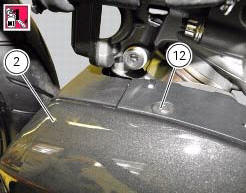
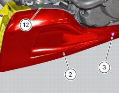
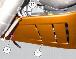
Apply recommended threadlocker on screws (3) and (12).
Fit the nylon washer (4) on the screw (3).
Fix the lh belly fairing (2) to the electrical components support by starting the screws (3) on the rear side, and the screw (12) on the upper side.
Apply recommended threadlocker to the screws (5) and (8).
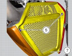
Fix the lh belly fairing (2) to the oil cooler shield (7) by starting the screw (8) on the lower side, and the screw (5) on the front side.
Fit the clips (9) on the rh belly fairing (1) orienting it as shown in the figure; follow the same procedure to refit the lh belly fairing (2).
Tighten to a torque of 4 nm +/- 10% (sect. 3 - 3, Frame torque settings) the screws (3), (5), (8) and (12) to fix the belly fairings (1) and (2) and the oil cooler shield (7).
 Removal of belly fairing
Loosen and remove the screws (5) and (8) that secure the oil cooler (7) to
the rh (1) and lh (2) belly fairings.
Remove the lh belly fairing (2) by loosening the screws (3) with relevan ...
 Electrical components support
Clip
Screw
Voltage regulator
Battery fixing bracket
Battery support
Vibration damper mount
Hose clip
Vibration damper mount
Clip
Washer
Screw
Cover
Cable grommet
Batte ...
Other materials:
Overhaul of the crankcase halves
Carefully examine the engine crankcase halves.
Check that the surfaces of the crankcase halves are perfectly flat using a
reference surface.
Check that the bearings (1) and (18), and the bushings (2) and (17) are in
optimum conditions. Note that the main
bearings must always be changed in p ...
Dashes shown instead of speed indication or indicated speed is incorrect
Fault codes
Dds: speed sensor diagnosis -> max. Speed (max. Speed error - signal not
correct) - minimum speed (min speed error -
signal not correct) - congruence (correlation speed error - signal not correct).
Dashboard: the error "speed sensor" is shown on the service display. The eobd
...
Inputs and outputs of engine control unit and connection to can network
The diagram illustrates the inputs and outputs for the engine control unit.
The signals from the brake buttons, the exhaust
by-pass valve command signal and the gear sensor signal are transmitted over the
can line.
1I emergency engine cutout switch
2I start button
4I side stand button
6 ...