
Ducati Diavel Service Manual: Low beam lights not working
Location of connections and components
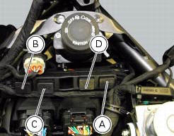
(A) injection relay; (b) etv relay (throttle valve operating engine); (c) radiator fan relay; (d) hands free relay.
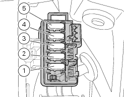
Fuses located at the rear left of the vehicle.
(1) 10A dashboard; (2) 5a engine control unit; (3) 15a key-sense; (4) 20a injection relay; (5) 10a throttle opening relay (etv).
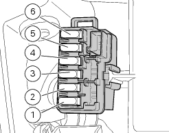
Fuses located at the rear right of the vehicle.
(1) 7.5A black box system (bbs); (2) 7.5A navigator/alarm; (3) 25a abs 2; (4) 30a abs 1; (5) 10a fans; (6) 7.5A diagnosis/recharge.
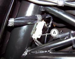
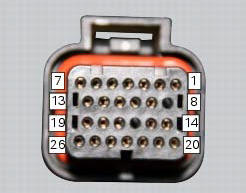
(A) low / high beam and parking light connections
 High beam lights not working
Fault codes
The hi beam light on the (slave) dashboard flashes at 1hz frequency.
Wiring diagram
Location of elements on motorcycle
(A) injection relay; (b) etv relay (throttle valve operating ...
 Horn not working
Fault codes
Dds: horn diagnosis -> short circuit to ground (s.C. Gnd).
Dashboard: the error "claxon" (horn) is shown on the service display. The eobd
warning light activates.
Wiring diagram
...
Other materials:
Overhaul of the cylinder barrel/piston components
Overhauling the cylinder
Check that the walls of the cylinder bore are perfectly smooth. Measure the
cylinder bore diameter at 50 mm from the top
face and determine the size class to which it belongs in accordance with the
values specified in sect. 3 -
1.1Cylinder/piston. Repeat measurement o ...
Refitting the steering head components
Important
The steering tube bearings (6) are identical but in no case may their
components be swapped around during reassembly.
Clean all contact surfaces and lubricate with the recommended grease.
To fit the external rings (c) of the bearings (6) to the steering tube, use the
tool with par ...
Refitting the front footrests
Note
The assembly of the front footrests is described only for the right one
(2) but it is the same also for the left one.
Place the spring (4) bringing the end (a) onto the footrest (2).
Place the footrest (2) in the correct position, by inserting the end (c) of the
spring (4) in the hole ...