
Ducati Diavel Service Manual: Inputs and outputs of engine control unit and connection to can network
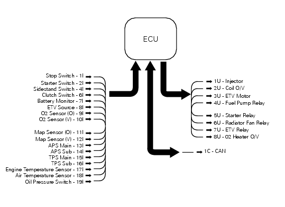
The diagram illustrates the inputs and outputs for the engine control unit. The signals from the brake buttons, the exhaust by-pass valve command signal and the gear sensor signal are transmitted over the can line.
1I emergency engine cutout switch
2I start button
4I side stand button
6I clutch button
7I battery voltage for congruence verification
8I power from ride-by-wire relay (etv)
9I oxygen sensor for horizontal cylinder
10I oxygen sensor for vertical cylinder
11I map sensor for horizontal cylinder
12I map sensor for vertical cylinder
13I main throttle grip position sensor
14I secondary throttle grip position sensor
15I main throttle valve position sensor
16I secondary throttle valve position sensor
17I engine temperature sensor
18I air temperature sensor
19I oil pressure switch (has no effect on any engine control strategy, but information is sent to dashboard via can line)
1U vertical and horizontal cylinder fuel injector
2U vertical and horizontal cylinder coil
3U electric ride-by-wire
4U injection relay (powers fuel pump, injectors and coils)
5U starter motor relay command
6U radiator fan relay command
7U ride-by-wire relay command
8U oxygen sensor heater for vertical and horizontal cylinder
1C connection with can network
 Specific operating strategies
Idle speed
No electric motor is used for idle speed regulation (bypass is modulated
instead with the throttle valve), as idle speed
control is effected by the ride-by-wire system. Idle speed is ma ...
 Layout of engine control system and other components
Injection relay
Etv relay (throttle valve operating engine)
Fan radiator relay
Hands free relay
Ecu
...
Other materials:
Cylinder/piston assemblies
Piston
Gudgeon pin circlip
Gudgeon pin
Set of piston rings
Cylinder-crankcase gasket
Water pump outlet union
Hose clip
Horizontal cylinder coolant inlet hose
Vertical cylinder coolant inlet hose
Cylinder barrel
Cylinder head gasket
Bush
Spare parts catalogue
Diavel a ...
Disassembly of structural components and the frame
Before carrying out dimensional checks on the frame, you must remove all the
superstructures fitted, referring to the
removal procedures outlined in the sections of this manual.
The rear subframes (2) and (3) are structural components of the frame (1).
Both serve to support motorcycle super ...
Final drive
Circlip
Nut
Washer
Nut
Rear sprocket flange
Cush drive bush
Inner ring
Chain
Spacer
Chain cover
Screw
Nut
Lock washer
Front sprocket
Spacer
O-ring
Rear sprocket
Spare parts catalogue
Diavel abs gearbox
Diavel abs rear wheel axle
Diavel carbon
abs
gearbo ...