
Ducati Diavel Service Manual: Inspection of the gear selector drum
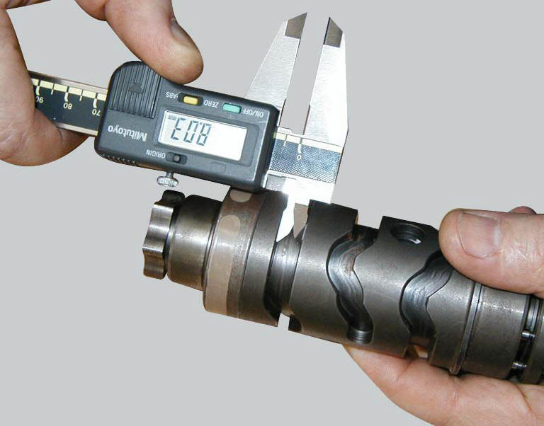
Use a gauge to measure the clearance between fork pin and the slot on the selector drum.
If the service limit is exceeded, determine which part must be replaced by comparing these dimensions with those of new components (sect. 3 - 1.1, Gearbox).
Also check the wear on the drum support pins; these must not show any signs of scoring, burrs, or deformation.
Turn the drum in the crankcase to establish the extent of radial play. If play is excessive, change whichever part is most worn.
 Inspection of the gear selector forks
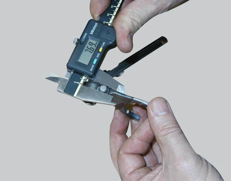
Visually inspect the gear selector forks. Bent forks must be renewed as they
may lead to difficulties in gear changing or
may suddenly disengage when under load.
Use a feeler gauge to check the ...
 Reassembly of the gearbox shafts
Figure 1 shows all the parts to be reassembled on the gearbox primary shaft
(2), with the calculated end shims (1) and
(11) (sec. 9 - 9.2, Reassembly of the crankcase halves).
Figure 2 shows a ...
Other materials:
Front brake control
Front brake master cylinder
Brake lever
Special screw
Sealing washer
Screw
Phonic wheel
Brake disc
Pin
Left brake calliper
Boot
Bleed valve
Spare stand
Control unit - front callipers pipe
Microswitch
Oil duct union
Screw
Hose clip
Right brake calliper
Speci ...
Riding style function (riding style change)
This function changes the motorcycle riding style.
Each riding style is associated with a different intervention
level of the traction control (dtc - ducati traction control)
and different engine power and output.
To change the motorcycle riding mode, press the reset
button once (12, fig. 1 ...
Ignition coils
Introduction
The engine control system of the diavel includes two ignition coils: one for
the horizontal cylinder and one for the vertical
cylinder. These coils are installed directly in the spark plug wells. A diode is
installed on the secondary winding inside the
coil, which prevents the un ...