
Ducati Diavel Service Manual: Lap registration function
This function describes the "lap" time registration.
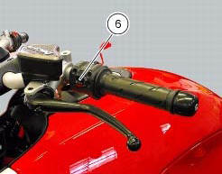
If the function is activated (see "lap activation/deactivation description), the lap time can be registered as follows: pressing the flash headlight button (6) the first time starts the "lap timer" for the first lap, and the dashboard shows the message "lap-start" flashing for 4 seconds, and then returns to the "previous" display; from this moment, each time that the flash (6) is pressed the display automatically shows the lap number and lap time for 10 seconds and then returns to the "previous" display.
You can save a maximum of 30 laps in the memory.
Once the memory is full, the dashboard no longer stores lap times when the flash headlight button (6) is pressed, and the flashing message "lap-full" is shown on the display for 4 seconds until the times are reset.
When the lap function is set disabled, the current "lap" is not stored.
If the lap function is active and suddenly the motorcycle is suddenly turned off (key-off), the function will be automatically disabled (even if the lap timer was active, the current "lap" is not stored).
If the time is never "stopped", it will roll over upon reaching 9 minutes, 59 seconds and 99 hundredths; the lap timer starts counting from 0 (zero) and will keep running until the function is disabled.
If however the lap function is switched on and the memory has not been cleared, but fewer than 30 laps have been saved (e.G. 18 Laps), the dashboard will store any remaining laps until the memory is full (in this case, it will store an additional 12 laps).
This function only displays the times for the lap being registered; but other data are also saved (max speed and max rpm) for viewing at a later date in the "lap data" function (stored lap display).
 Lap activation/deactivation function (lap time)
This function activates and deactivates the lap function (lap time).
To access the function it is necessary to view the ""setting" menu", using
buttons (1) "s" or (2) "t" select the "lap"
functi ...
 Stored lap display function
This function displays the stored laps.
To access the function it is necessary to view the ""setting" menu", using
buttons (1) "s" or (2) "t" select the "lap"
function and press the reset button ...
Other materials:
Coverage
Warranty defects shall be remedied during customary
business hours at any authorized ducati motorcycle dealer
located within the united states of america in compliance
with the clean air act and applicable regulations of the
united states environmental protection agency and the
california air r ...
Units of measurement modification function
This function allows you to change the units of measurement of the displayed
values.
To access the function it is necessary to view the ""setting" menu", using
buttons (1) "s" or (2) "t" to select the "set
units" function and press the reset button (3) to enter the following page.
Use but ...
Refitting the flywheel-alternator assembly
Fit the roller cage unit (20) with washer (18) and internal ring (19),
applying prescribed grease on the washer (18).
Install the roller cage assembly (20) with the washer (18) and inner race
(19).
Install the flywheel assembly (v) with the gear (21), aligning the notches as
shown in ...