
Ducati Diavel Service Manual: Radiator fan relay
Introduction
The radiator fans are powered via a specific relay, which is enabled by the engine control unit.
Component assembling position
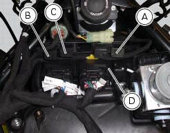
A injection relay; b etv relay (throttle valve actuator motor), c radiator fan relay, d engine control unit.
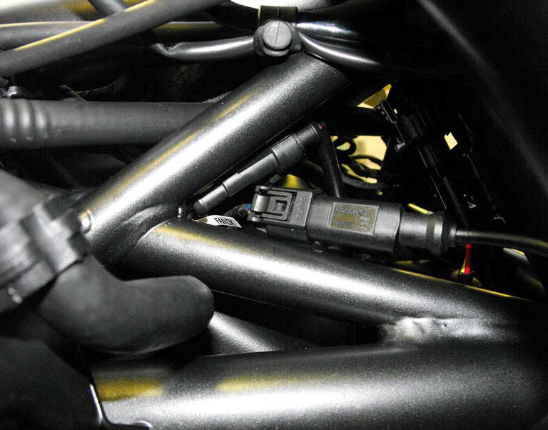
Location of right hand fan connection.
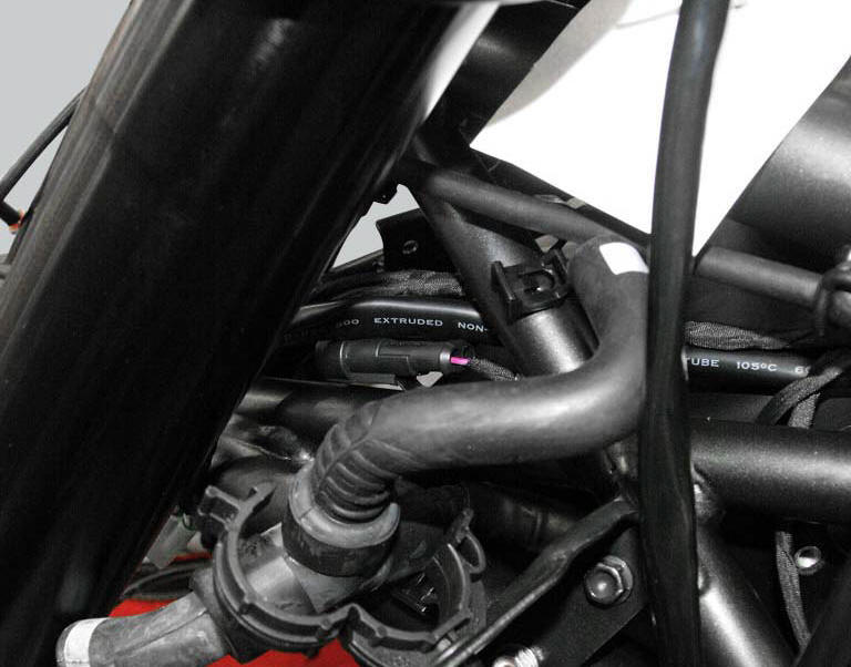
Location of left hand fan connection.
Connection wiring diagram
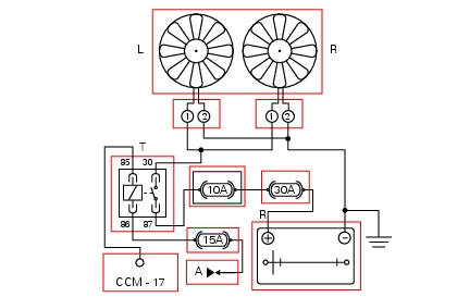
Ccm engine control connection, t radiator fan relay, a key on power (+15 from hands free relay 30), r battery power (+30), l left hand fan, r right hand fan, 85 light blue/black - lb/bk, 30 red/green - r/g, 86 red/black - r/bk, 87 red/grey - r/gr.
In the event of fault
In the event of a radiator fan relay fault, the radiator fans themselves do not work. The relay is not commanded by the ecu.
Fault codes generated and possible correlated faults fault codes generated by the engine control unit and displayed by the dds (fan relay diagnosis):
- Open circuit: check integrity of fuses, electrical circuit and electrical connections
- Short circuit to ground: check integrity of fuses, electrical circuit and electrical connections
Note
Check integrity of electric circuit - short-circuit to vdc = with dashboard on, using a voltmeter, a voltage is measured between the wire tested and ground.
Check integrity of electric circuit - short-circuit to ground = with the battery cables disconnected, using an ohmmeter, continuity is detected between the wire tested and ground.
Check integrity of electric circuit - open circuit = with the battery cables disconnected, using an ohmmeter, no continuity is detected between the two ends of the wire tested.
The dashboard service display shows the error "fan relay" and the eobd warning light activates.
Possible correlated faults: coolant reaches boiling point but radiator fans not working. Check:
- Integrity of fuses.
- If power supply voltage (12 v - key on) is present on pin 86 of the radiator fan relay (if not, consult the paragraph "hands free").
- Radiator fan function. After removing from its mounting, apply 12 v power to pin 85 and pin 86 and check that pin 87 and pin 30 close (continuity between pins).
- Integrity of the connections and electrical circuit between the relay and the radiator fans.
- The engine temperature sensor (see "engine temperature sensor of this section").
- State of cooling circuit (fluid must be filled to correct level and there must be no air in the circuit).
The radiator fan relay may be actuated from the dds to check radiator fan function.
The fans are normally activated at 103 and switched off at 101C.
If none of the aforementioned tests identify the problem and the radiator fan relay is in proper working order, replace the engine control unit.
Component replacement methods
No special measures are necessary in order to replace the radiator fan relay.
 Starter motor relay
Introduction
When the rider presses the start button, with all the safety conditions
required to enable engine start met, the engine
control unit enables the relay that activates the starter motor ...
 Engine speed-timing sensor
Introduction
The engine control system of the diavel is equipped with an inductive sensor
that allows the ecu to determine the speed
and timing phase of the engine. The sensor faces a phonic wheel ...
Other materials:
Reassembling the water radiator unit
The procedure is the same for both radiators.
Check the presence of clips (1) at the positions of the external coolant
radiator cover (23).
If removed, fit the front turn indicator (32) on the cover (23) and tighten the
screws (27) to 2 nm +/- 10% (sect. 3 - 3,
Frame torque settings).
No ...
Refitting the front brake system
While refitting the system, pay special attention to the orientation of the
pipe couplings (24) on the pump and the pipes
(13) and (20) on the callipers (9) and (18).
Warning
If incorrectly positioned, the hose can affect brake operation and
foul moving parts. Position the hose as shown in th ...
Refitting the handlebar
Position the handlebar (4) so that the external lower corner of the marks (a)
on the handlebar matches the upper internal
corner of the lower u-bolts (b) as shown.
Apply the recommended grease to the threads and undersides of the heads of
the screws (3).
Important
Position the upper u-bo ...