
Ducati Diavel Service Manual: Starter motor relay
Introduction
When the rider presses the start button, with all the safety conditions required to enable engine start met, the engine control unit enables the relay that activates the starter motor.
Component assembling position
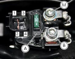
Connection on starter motor relay.
Connection wiring diagram
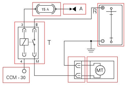
Mt starter motor, ccm engine control connection. 4 Starter motor relay activation, blue/black - b/bk, a key on power (+15 from hands free relay 30), r battery power (+30), 3 red/black - r/bk, m black - bk, b black - bk.
In the event of fault
In the event of a starter motor relay fault, the engine will not start.
Fault codes generated and possible correlated faults
The engine control unit generates no fault code in the event of a starter motor relay fault.
No errors are indicated on the dashboard.
Possible correlated faults: the starter motor cannot be operated. Check:
- Battery state of charge
- If power supply voltage (12 v - key-on) is present on pin 3 of the starter motor relay (if not, consult the paragraph "hands free") and check the integrity of the 15a fuse
- Integrity of the electrical circuit and electrical connections of the starter motor relay
- Integrity of the starter motor relay. After removing the relay, when 12 v power is applied to pin 3 and pin 4, the contacts should close (continuity between pin b and pin m)
- Integrity of the starter motor and that the motor is correctly connected to the electrical system (also check ground Connection on engine, see sect. 6 - 3"Starter motor")
- The integrity of the engine start button and its circuit
- The integrity of the side stand switch, the clutch lever switch, the gear position sensor and their respective circuits
- Integrity of stop engine switch
Note
Check integrity of electric circuit - short-circuit to vdc = with dashboard on, using a voltmeter, a voltage is measured between the wire tested and ground.
Check integrity of electric circuit - short-circuit to ground = with the battery cables disconnected, using an ohmmeter, continuity is detected between the wire tested and ground.
Check integrity of electric circuit - open circuit = with the battery cables disconnected, using an ohmmeter, no continuity is detected between the two ends of the wire tested.
If none of the tests described above identifies the problem and the power supply and ground for the engine control unit are in correct working order, replace the engine control unit.
Component replacement methods
No special measures are necessary in order to replace the starter motor relay.
 Throttle valve actuator motor relay
Introduction
The throttle valve actuator motor is powered by the engine control unit. The
engine control unit receives the necessary
power from a specific relay.
Component assembling position
...
 Radiator fan relay
Introduction
The radiator fans are powered via a specific relay, which is enabled by the
engine control unit.
Component assembling position
A injection relay; b etv relay (throttle valve actu ...
Other materials:
Riding modes
The rider may select between four different riding modes (sport, touring,
urban and enduro) from the dashboard and via
the "turn indicator reset" button (3). Each riding mode contains settings for
the following:
The dtc set-up (sect. 6 - 7 "Dtc (ducati traction control) setting
function" ...
Checks and adjustments
Closing shim
Intake side camshaft
Opening shim
Exhaust side camshaft
Valve
Spare parts catalogue
Diavel abs cylinder head: timing system
Diavel abs vertical cylinder head
Diavel abs horizontal cylinder head
Diavel carbon
abs
cylinder head: timing system
Diavel carbon
abs
v ...
Adjusting the position of the gearchange and rear brake
pedals
The position of the gearchange and rear brake pedals in
relation to the footrests can be adjusted to suit the
requirements of the rider.
Adjust the pedals as follows:
Gear change pedal (fig. 97)
Hold the linkage (1) and slacken the lock nuts (2) and (3).
Note
Nut (2) has a left-hand thr ...